Installation #
Start by placing the Reclaim System per the instructions listed in the previous section.
System Connections #
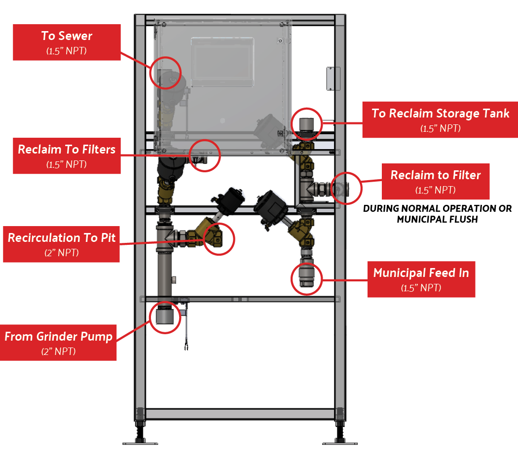
fig. 1.1 – 1 – Reclaim System connections
SEG Pump Installation #
The SEG (grinder pump) should be installed in the clarifying tank (fig. 4.2).
- Mount SEG pump to base using included hardware and gasket.
- Attach 2” hose to the outlet of the SEG base using a 2” NPT hose barb.
- Lower SEG into last division of the settling tanks with the provided lifting chain.
- Connect the 2” hose to the Reclaim manifold using another 2” hose barb.
- Run the wire from the SEG pump to the control box as described
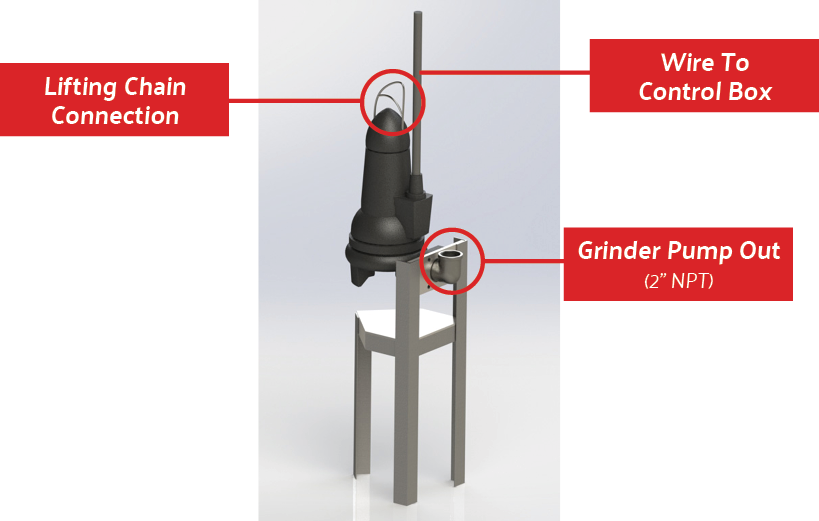
fig 1.2 – SEG Pump Installation
Bubbler Installation #
- Attach chain, or rope, to the holes on each end of the bubbler frame (fig. 4.3 – 1).
- Attach 3/8” polytube to the push connect between the two bubbler discs installed in the tank so it can be routed properly.
- Using the chain or rope attached to the bubbler frame, lower the bubbler into the second-to-last section of the settling tanks.
- Route the 3/8” polytube to the outlet of the airflow meter on the front of the Reclaim System’s main frame (fig. 4.3 – 2). The flow meter should be set to roughly 2 cfm.
- The bubbler frame’s feet keep the bubblers above settling dirt and debris. However, the bubbler may also be suspended using the chain or rope if your settling tanks go long periods between cleanings.
- It is recommended to suspend the bubbler while the tank is empty to verify that it sits level while suspended.
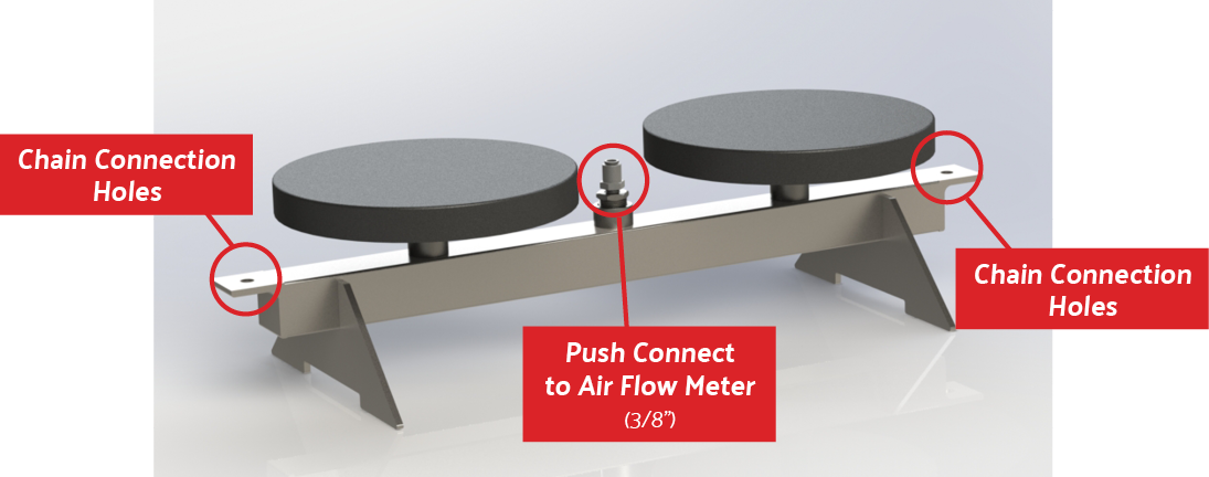
fig 1.3 – 1 – Bubbler Installation
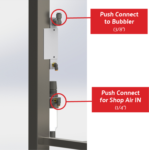
fig 1.3 – 2 – Bubbler Pneumatic Connections
Multimedia Filter Installation #
- Place the filter frame(s) in the desired location(s). The High Flow system filter frames can be secured together using the bolt holes on the on the frame if that is the planned installation configuration (fig. 4.4).
- Plumb the “Dirty” side from the tee on the reclaim manifold to the 1.5” NPT opening on the “IN” side of the filter manifold.
- High Flow System Only – Connect the reclaim manifold to the filter set with a 1.5” NPT opening on both ends.
- Next, connect the 1.5” NPT opening in the front of the manifold to the 1.5” NPT opening on the other set of filters.
- The opposite end of the second filter manifold will be plugged.
- Plumb the “Clean” side from the tee on the flush manifold to the “OUT” side of the filter manifolds.
- High Flow System Only – Connect the reclaim manifold to the filter set with a 1.5” NPT opening on both ends.
- Next, connect the 1.5” NPT opening in the front of the manifold to the 1.5” NPT opening on the other set of filters.
- The opposite end of the second filter manifold will be plugged.
- High Flow system filters can be laid out in the backroom as desired by the operator. However, the “IN” and “OUT” sides of the filters must be connected to each other for the system to flow properly.
- It is also recommended to keep plumbing between the filter assemblies as short as possible to reduce the pressure drop across the individual filters.
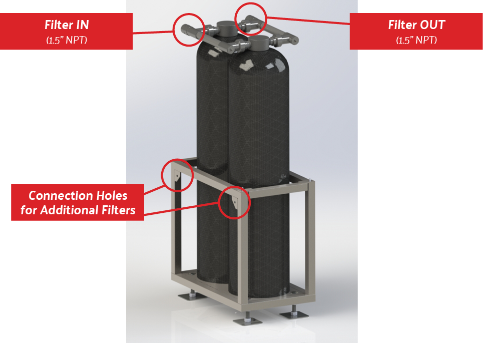
fig 1.4 – Multimedia Filter Installation
Main Frame Installation #
The main frame containing the control box and valve manifolds should be located as close to the settling tanks as possible to reduce the amount of plumbing needed.
- Connect a 1.5” municipal water feed to the bottom of the “Flush Manifold” (fig 4.5 – 2). There is a check valve to ensure that no reclaim water can get into the municipal feed in the event of serious filter failure.
- It is recommended to have a shut of valve on the municipal line before the Reclaim System so water can be shut off for maintenance.
- Plumb your reclaim storage or pump stand tanks to the top 1.5” NPT connection on the “Flush Manifold” (fig 4.5-2).
- Plumb the top 1.5” NPT connection on the “Reclaim Manifold” to the sewer.
- It is important that this water is removed from your reclaim water loop because it contains everything the filters have pulled from your reclaim water. Introducing this water back into the loop concentrates the water with the removed particles and rapidly increases the pressure drop across the filters.
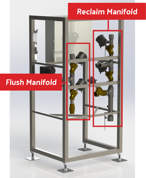
fig. 1.5 – 1 – Rear of Main Frame
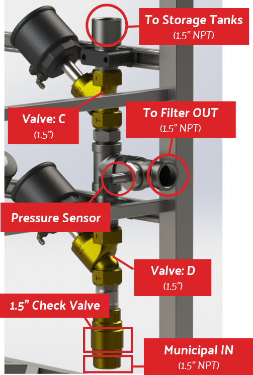
fig. 1.5 – 2 – Flush Connections
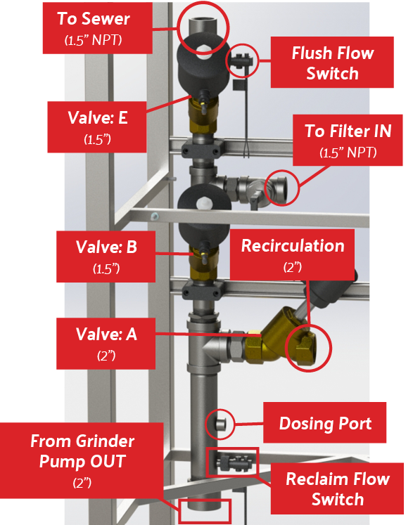
fig. 1.5 – 3 – Reclaim Connections
Electrical Installation #
! WARNING !
TO BE PERFORMED BY A QUALIFIED ELECTRICIAN
The electrical schematics and connection points can be found in the Reclaim System control box.
NOTE: Each controller has a serial number located inside the controller on the lower left side of the housing (fig 4.6 – 1-2). This location is shown in the picture below and should be used when requesting support on the Reclaim System, as this number links to both the controller software and hardware.
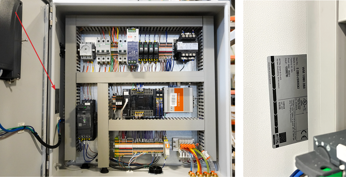
fig. 1.6 – 1 – Serial number location
IMPORTANT: Follow all local codes.
Main Control Fuse Block (FB1) – Bussmann LP-CC-15 fuses are used for the 480VAC primary
MOTOR Protection Circuit Breaker (M1) – Sized for motor. This provides short circuit protection to the motor as well as thermal overload protection.
DC Power Supply (PS1) – Converts 480VAC to 24VDC for control circuit components.
PLC (PLC) – Programmable Logic Controller – Executes a program that controls the sequence and times of the operation through I/O (inputs and outputs).
HMI (HMI) – Human Machine Interface – Executes a graphical interface program that communicates with the PLC to let the operator know the state of the equipment.
Run 3 phase 480VAC into the enclosure from bottom (left side) through the wire railway and connect to the main power switch of the unit (fig. 4.2 – 3).
Control Relay (CR1) – Land the 24VAC request for reclaim water signal from the tunnel to this component (fig. 4.6 – 3).
This command will produce reclaim water each time the belt command is given. The unit will continue to run after the belt command is removed for a programmable time to allow refilling the Reclaim tank.
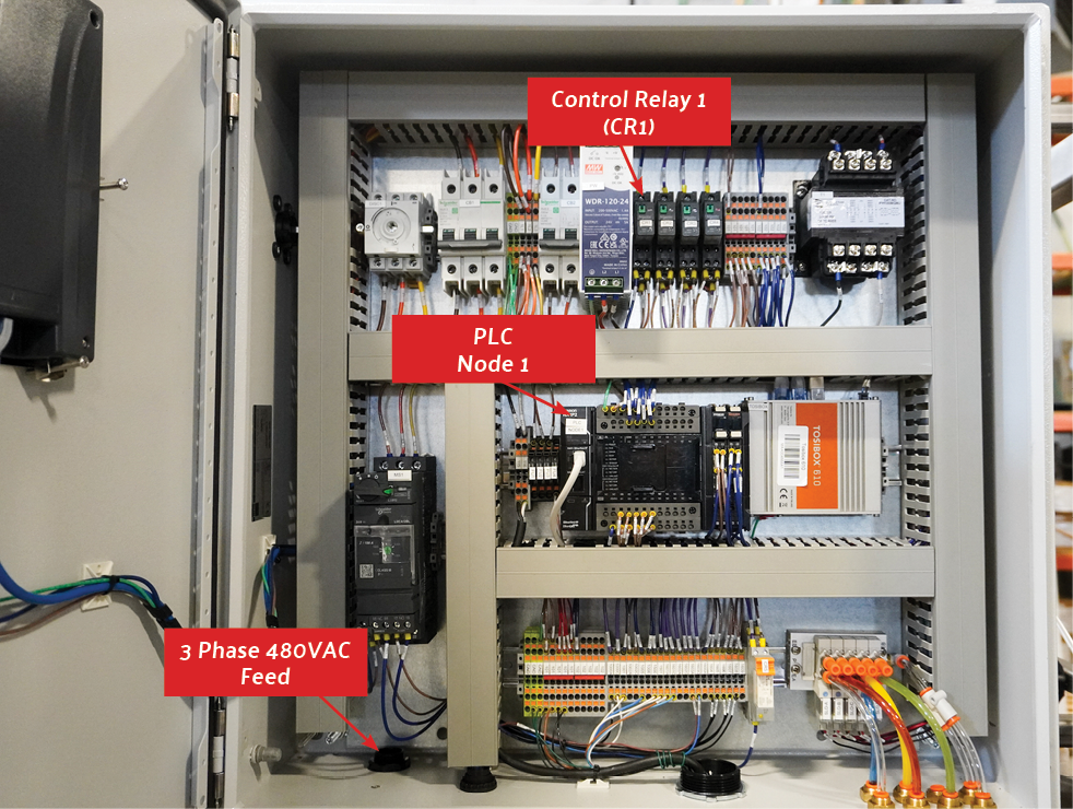
fig. 1.6 – 2 – Reclaim System Control Box Connections