3. Installation #
Installation of the dispenseIT must conform to local plumbing, electrical, and sanitation codes. The customer is responsible for obtaining all permits and ensuring the following conform to all state and local codes before installing the dispenseIT.
3.1 Installation Preparation #
Locate where the dispenseIT will be installed with your installer. Take into consideration the following points:
- Location of the water supply, air supply, and 3PH electrical supply for the dispenseIT
- Location of the control wiring from tunnel controller for the dispenseIT
- Location of any equipment that may be spraying water
- Distance from the dispenseIT to the applicator arches
Refer to Fig. 3.1 – 1 for solenoid, air regulator, and valve alignment for each function.

Fig. 3.1 – 1 – Solenoid, air regulator, foaming ports, and valve alignment
3.2 Mechanical Installation #
Place equipment in the equipment room where the installation will take place. If possible, have the unit away from areas where the pump could take a direct spray from liquids.
- Floor Mount: Turn the swivel casters so the wheels point forward and lock in place to ensure maximum stability
- Safety chain is required.
- Wall Mount: Mounting hardware and wall must be capable of supporting unit’s weight. Place the pump on the floor to the right of the unit.
- Be sure to install the supplied stainless steel guard around the pump’s base to avoid damage by barrels, barrel carts, etc.
- Recommended height is at least 4’, measured from the bottom of the frame to the floor.

Fig. 3.2 – 1 – 20 Function Floor Mount dispenseIT
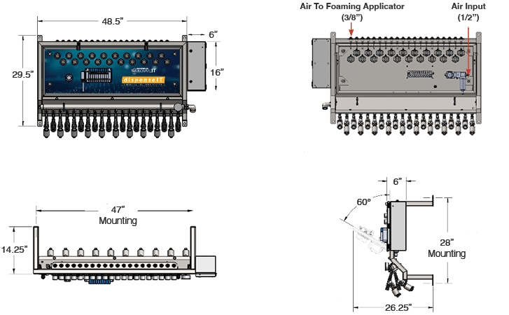
Fig. 3.2 – 2 – 20 Function Wall Mount dispenseIT
3.2.1 Installing Water Lines #
NOTE: If installing the optional innovateIT-supplied particle filter, install it inline on the Main Water Inlet side of the pump.
- Install the water feed line to the location of the dispenseIT (2” for 7.5 HP pump, 1.25” for 5 HP pump).
-
- Existing Buildings – Flush the new water line for a minimum of 5 minutes to ensure that any debris in the water line is completely flushed out.
- New Buildings – Flush the water line for a minimum of 15 minutes to ensure that any debris in the water line is completely flushed out.
!WARNING! Failure to flush water lines prior to connecting to and operating the pump could lead to catastrophic failure of the Grundfos pump
- Install water feed line to the inlet side of the pump using appropriately sized fittings based on pump size (Fig. 3.2.1 – 1).
- Install hose from the pump discharge to the dispenseIT manifold using the following steps.
- Connect supplied fittings (shipped with injectors) to the manifold side of the hose.
- Standard: Assembly order is: nipple, 1” elbow, hose barb.
- Split Manifold: Assembly order is: nipple, 1” street elbow, check valve, hose barb.
- Hose Length:
- Wall Mount: Shipped with 6’ hose. Hose may be shortened if =desired.
- Floor Mount: Hose is factory-installed and shipped cut to correct length.
- Thread other hose end into pump discharge.
- Connect nipple to swivel fitting on the manifold.
- Tighten hose clamps appropriately.
- Connect supplied fittings (shipped with injectors) to the manifold side of the hose.
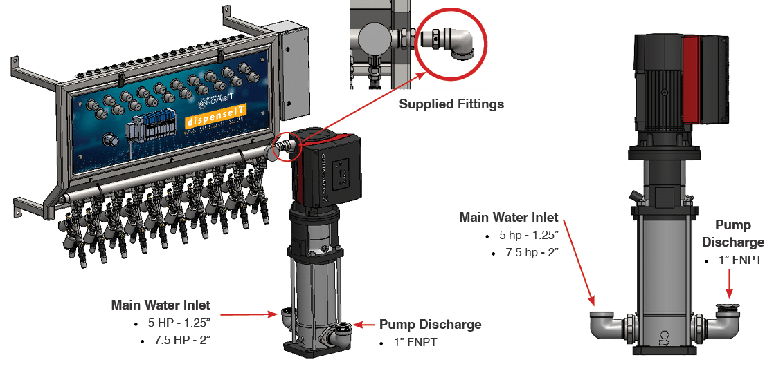
Fig. 3.2.1 – 1 – Water lines connections
3.2.2 Installing Main Air Line #
Install main airline feed to inlet side of the Main Air Regulator (Fig. 3.3.2 – 1).
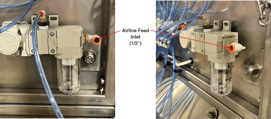
Fig. 3.2.2 – 1 – Airline feed to Main Air Regulator
3.2.4 Installing Liquid and Air Connections for Functions #
NOTE: High Flow injectors (above 5 gpm) require ¾” process line.
- Connect 1/2” poly tube (Standard Flow injector) or 3/4” Boston hose (High Flow injector) liquid lines to the appropriate injector port as specified in your customer configuration form (Fig. 3.2.4 – 1).
- Connect 3/8” poly tube air lines to the appropriate foam port on top of the system that aligns to the corresponding process valve. Functions are identified 1-10, 1-15, or 1-20 from left to right.
- Turn on water and line supplies and check for leaks.
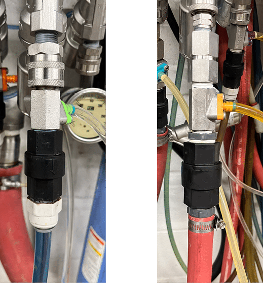
Fig. 3.2.4 – 1 – Liquid connection to Standard Flow (left) and High Flow (right) injector port
3.2.5 Installing Airgun Kit (Optional) #
- Turn off the main air supply to the unit.
- Manually actuate any control valve to relieve air pressure in the system.
- Remove the 1/4” plug from the underside of the Main Air Regulator assembly (Fig. 3.2.5. – 1).
- Install 1/4” push connect elbow into the port.
- Install bulkhead fitting into the lower left hole on the bottom panel with threaded fitting pointing towards the front of the unit (Fig. 3.2.5 – 2).
- Use supplied hardware to bolt the bracket to the underside left of the frame
- Install the air hose into the bulkhead fitting.
- Install the airgun attachment to the hose.
- Connect poly tube from the elbow to the back side of the bulkhead fitting.
- Turn on the main air supply to the unit.
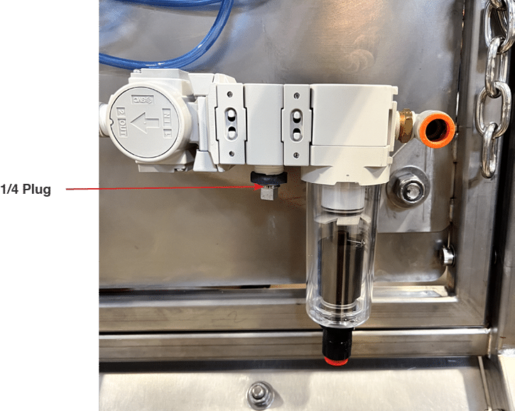
Fig. 3.2.5 – 1 – 1/4” plug on Main Air Regulator
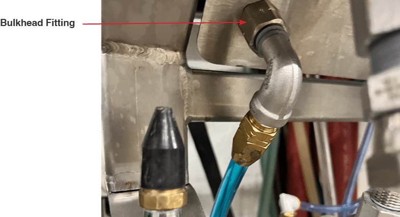
Fig. 3.2.5 – 2 – Bulkhead fitting for Airgun kit
3.3 Electrical Installation #
!WARNING! Electrical installation to be performed by a qualified electrician. Follow all local codes. 3PH breaker power to be supplied by customer.
NOTE: The Pump Run cable is supplied with the unit on Wall Mount systems.
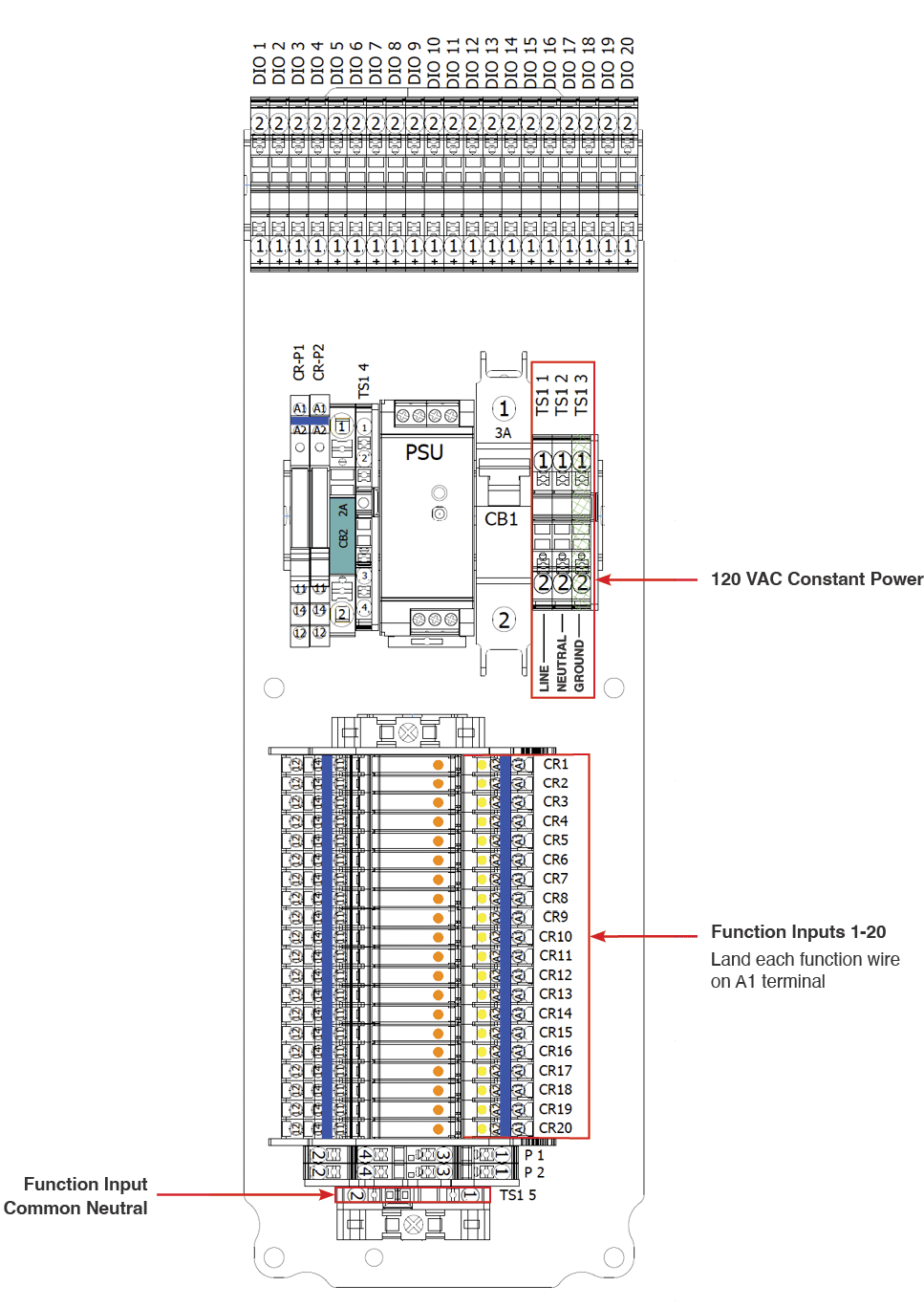
The electrical schematics and connection points in the controller are designated in Appendix 4.
- Confirm system voltage prior to starting electrical installation.
- Install the pump’s electrical connections.
- Use the bottom hole of the pump’s electrical box for the 3PH incoming power. Wire conductors to the L1, L2, and L3 conductors (Fig. 3.3 – 1).
- Connect the grounding conductor to the ground lug (Fig. 3.3 – 2).
- Connect the 3PH power to the pump’s terminal strip (terminal wiring plug can pull out for wiring ease). Inspect to ensure the terminal plug is fully seated.
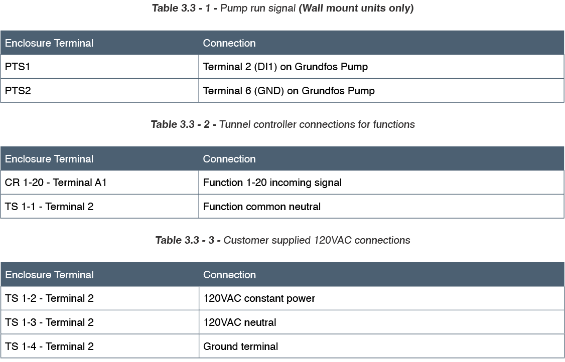
- Make electrical connections as listed in tables 3.3 – 1 to 3.3 – 3.
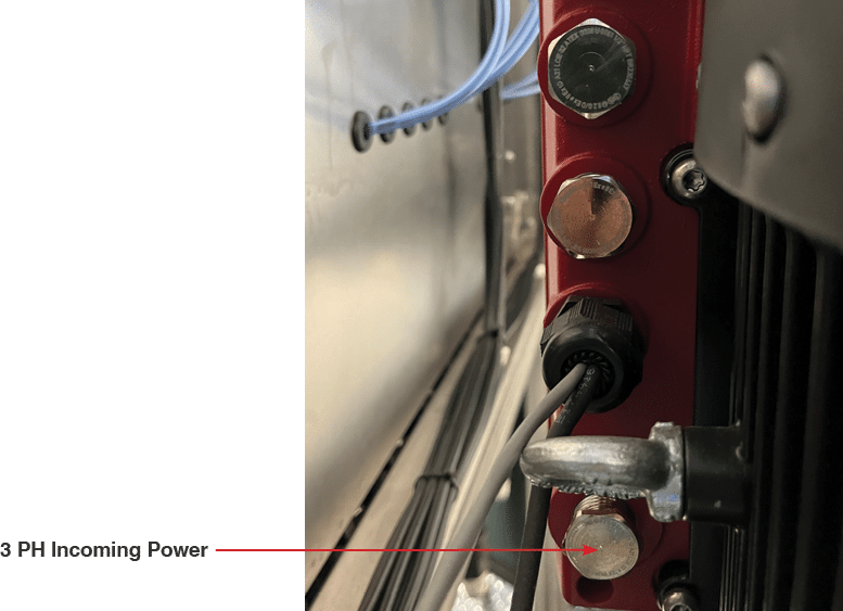
Fig. 3.3 – 1 – Pump 3 PH incoming power connection
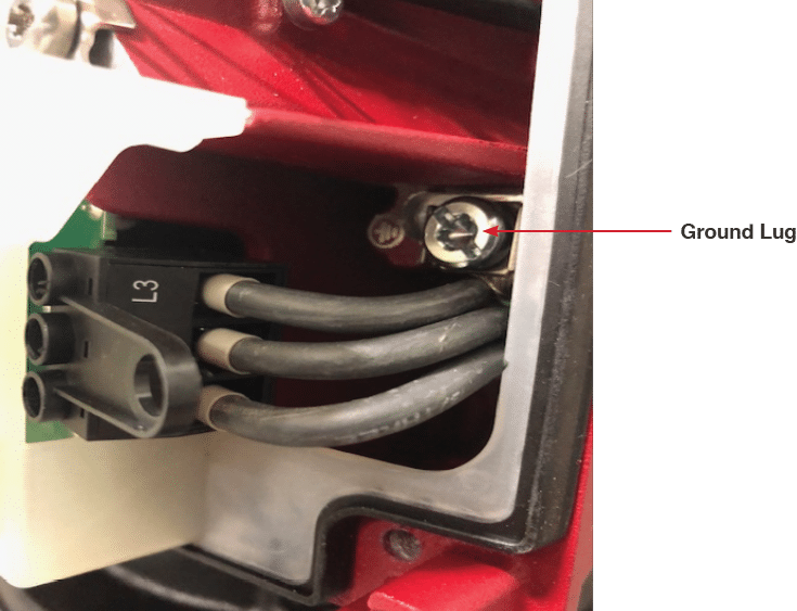
Fig. 3.3 – 2 – Pump grounding conductor and ground lug
NOTE: Voltage from the tunnel controller relay matches that of the coils on the dispenseIT (110 VAC, 24 VAC, or 24 VDC).