Installation of the dispenseIT must conform to local plumbing, electrical, and sanitation codes. The customer is responsible for obtaining all permits and ensuring the following conform to all state and local codes before installing the dispenseIT.
Place equipment in the equipment room where the installation will take place. If possible, have the unit away from areas where the pump could take a direct spray from liquids.
Floor Mount: Turn the swivel casters so the wheels point forward and lock in place to ensure maximum stability.
Safety chain: Not required.
Wall Mount: Place the pump on the floor to the right of the unit.
Install a stainless steel guard around the pump’s base to avoid damage by barrels, barrel carts, etc.
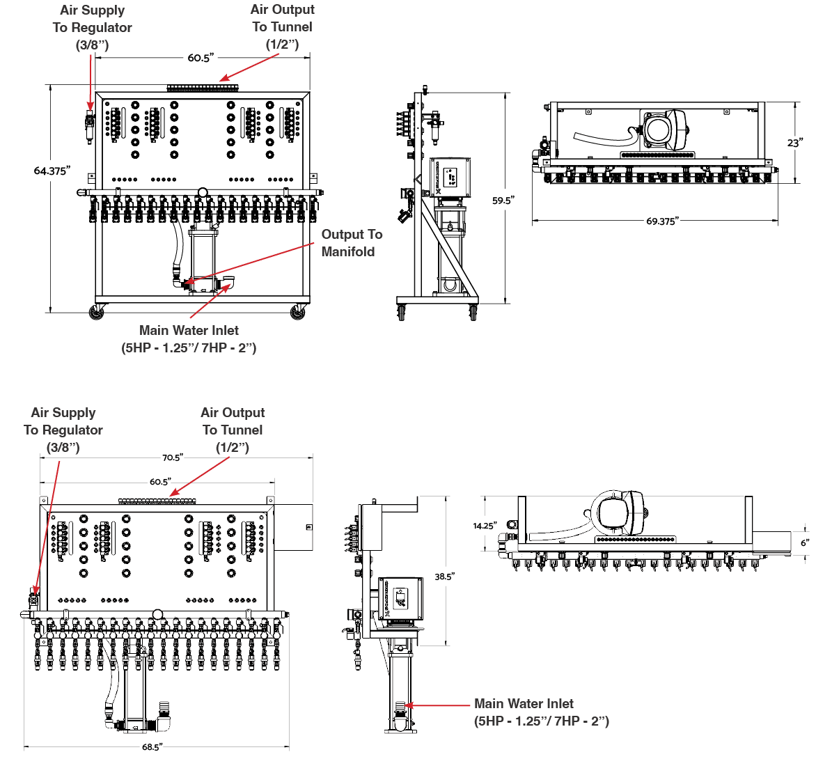
Recommended height is at least 4’, measured from the bottom of the frame to the floor.
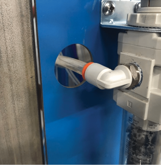
Install the main airline feed to the inlet side of the Main Air Regulator.
Fig. 3.2.2 – 1 – Airline feed to Main Air Regulator
3.2.3 Installing Liquid and Air Connections for Functions#
NOTE: High Flow injectors (above 5 GPM) require a ¾” process line.
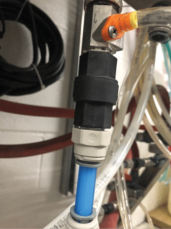
Connect ½” liquid lines to the appropriate injector port as specified in your customer configuration form. (Fig. 3.2.3 – 1)
Fig. 3.2.3 – 1 – Liquid connection to injector port
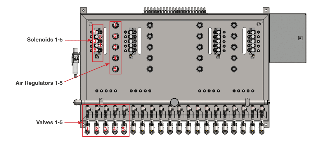
Connect 3/8” poly tube air lines to the appropriate foam port on top of the system as specified on the customer configuration form. Functions are identified 1-10, 1-15, or 1-20 from left to right.
Turn on water and line supplies and check for leaks.
WARNING: Electrical installation must be performed by a qualified electrician. Follow all local codes. 3PH breaker power must be supplied by the customer.
The electrical schematics and connection points in the controller are designated in Appendix 4.
Confirm system voltage prior to starting electrical installation.
Install the pump’s electrical connections.
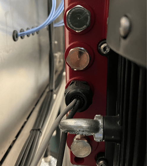
Use the bottom hole of the pump’s electrical box for the 3PH incoming power (Fig. 3.3 – 1)
Fig. 3.3 – 1 – Pump 3PH incoming power connection
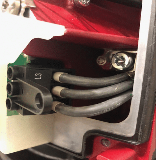
Connect the grounding conductor to the ground lug (Fig. 3.3 – 2).
Connect the 3PH power to the pump’s terminal strip (terminal wiring plug can pull out for wiring ease). Inspect to ensure the terminal plug is fully seated.
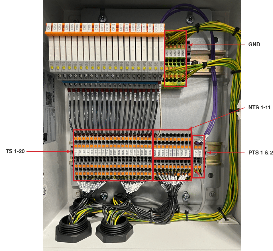
Make electrical connections as listed in the tables below.
NOTE: Voltage from the tunnel controller relay matches that of the coils on the dispenseIT (110VAC, 24VAC, or 24VDC).
Enclosure Terminal Connection
Details
PTS1
Terminal 2 on Grundfos Pump
PTS2
Terminal 6 on Grundfos Pump
TS 1-20
Tunnel controller normally open relay
NTS 1-11
1 neutral wire any of NTS terminals (from same power source that works with the power from the tunnel controller relay)
The dispenseIT arrives with any High Flow injectors installed from the factory. Standard Flow injectors are shipped with the unit. Installation of Standard Flow injectors is done via provided quick connectors.
Install metering tips into the barb of the injector. Consult your chemical solutions provider for dilution rates.
Install a ¼” chemical compatible hose from the chemical barrels to the injector barb.
Install chemical compatible foot valves for each function on the draw side of the hose (the part of the hose that rests inside of the product barrel).
It is recommended to use a 3’ piece of PVC pipe for the line to run through to keep the suction straight down in your chemical barrel.