3. Installation #
Installation of high-pressure arches must conform to local plumbing, electrical, and sanitation codes. The customer is responsible for obtaining all permits and ensuring the following conform to all state and local codes before installing the arch.
3.1 Installation Preparation #
NOTE:Dimensions of the arch are adjustable. The maximum width from outside to outside of the uprights in 149”.
Locate where the arch will be installed with your installer. Consider the following factors:
- Ensure a reliable municipal water supply is accessible and capable of meeting the system’s flow and pressure requirements.
- Verify the availability of a 208/230/480VAC 3-phase power source for the motors.
- Confirm sufficient space for the arches within the tunnel layout. The placement should allow for unobstructed vehicle travel and proper alignment of the manifolds with the vehicle surfaces for effective cleaning and rinsing.
3.2 Mechanical Installation #
NOTE: Manifolds come pre-mounted to the arch when delivered. They are positioned at specific heights to ensure an optimal spray pattern and coverage. If needed, the height can be adjusted to fine-tune performance based on the user’s specific setup.
Place equipment in the tunnel where the installation will take place. Position the arch to align with the centerline of the vehicle path. Refer to Fig. 3.2 – 2 for a visual representation of proper placement in the car wash tunnel.
Standard Conveyor
-
- Driver Side
- The center of the driver-side leg should be 40.5” off the conveyor’s inner rail.
- Passenger Side
- The center of the passenger-side leg should be 96.5” from the conveyor’s inner rail.
- Driver Side
Belt Conveyor
-
- The center of the arch should be aligned with the centerline of the belts.
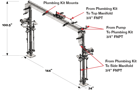
Fig. 3.2 – 1 – blastIT Arch connection points
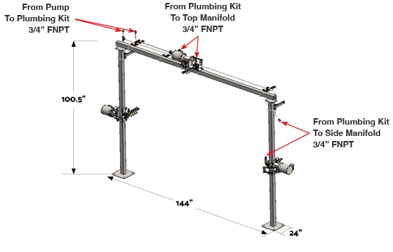
Fig. 3.2 – 2 – rinseIT Arch connection points
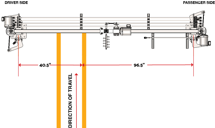
Fig. 3.2 – 3 – Standard chain conveyor placement of the blastIT Arch
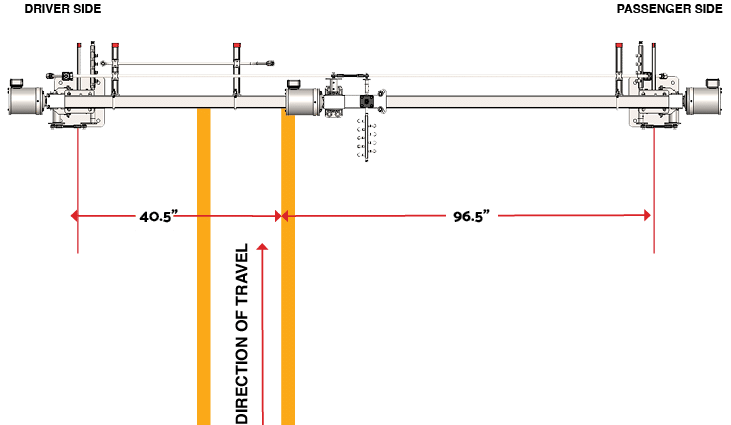
Fig. 3.2 – 5 – Standard chain conveyor placement of the rinseIT Arch
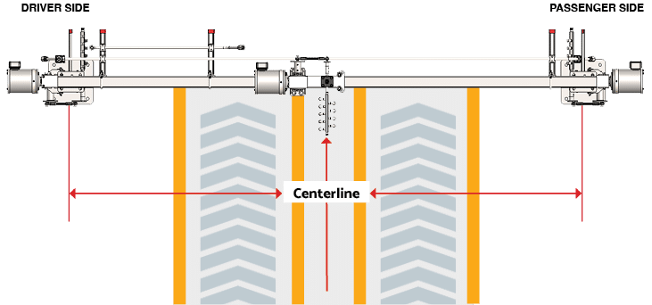
Fig. 3.2 – 6 – Belt conveyor placement of the rinseIT Arch
3.2.1 Assembling The Bare Arch #
Refer to Fig. 3.2 – 1 for the correct placement of the arch within the car wash tunnel.
- Align the arch with the vehicle centerline and confirm spacing from the conveyor’s guide rails.
- Lay the two 8-foot tall legs and the 12-foot crossbar on the ground near the intended installation site.
- Position one leg on the driver’s side of the conveyor and the other on the passenger’s side.
- Align the 12-foot crossbar perpendicular to the conveyor.
- Insert two ½” stainless steel U-bolts into the holes at the top of each leg (Fig. 3.2.1 – 1).
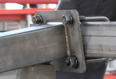
Fig. 3.2.1 – 1 – Attaching arch legs to crossbar
- Place ½” flat washers and split lock washers onto the bolts, then secure with ½” nuts.
- Slide the crossbar under the U-bolts on both legs and tighten the bolts snugly.
- Ensure the vertical legs and the crossbar are level.
- Floors are often pitched for drainage, so it is crucial to level the vertical legs accordingly. The crossbar should also be leveled, keeping in mind that the pitch may differ on the driver and passenger sides to allow for proper water drainage.
- Stainless steel flat-bar (1/8”x2”, 1/4”x2”) or 3/4” fender washers can be used under the floor plate for leveling as needed.
- Secure the arch to the floor using appropriate anchors. It is recommended to use 5/8”x 7” stainless steel thunder studs for optimal stability and durability.
3.2.2 Installing and Connecting Drive Linkages #
- Apply antiseize lubricant to all threads on bolts and hardware to prevent corrosion and ensure smooth assembly.
- Attach the drive linkages.
- Insert a shoulder bolt through the spherical rod end.
- Place a flat washer over the bolt and thread the nut onto the bolt the entire way.
- Insert the bolt into the threads on the pitman arm or flywheel and tighten securely.
- While holding the shoulder bolt with an Allen wrench, use a 9/16” wrench to tighten the nut down to the pitman arm/flywheel to use it as a jam nut.
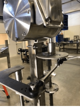
Fig. 3.2.2 – 1 – Flywheel/pitman arm connection
- When 2 linkage share a same shoulder bolt, place a flat washer between the 2 spherical rod ends (Fig. 3.2.2 – 2).
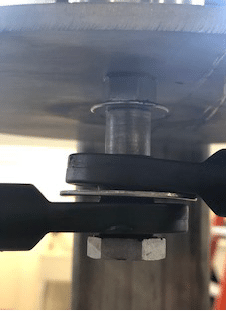
Fig. 3.2.2 – 2 – Installation of 2 linkages on 1 shoulder bolt
- Adjust the horizontal drive linkage to ensure it is level.
- If the linkage is not level, adjust the height of the gearbox or motor assembly.
- Grease all bearings.
The amount of oscillation (throw) of each manifold can be adjusted in two ways:
- Adjust the shoulder bolt location in the flywheel.
- Adjust the shoulder bolt location on the manifold’s pitman arm.
3.2.3 Installing Plumbing #
NOTE: When making hose connections, it is best to keep the mounts on the vertical legs as close as possible to the connection points of the tubing for stability
- Attach the tubing to the arch using clamps.
- Space the clamps evenly along the vertical legs and top crossbar.
- Attach the high-pressure hose from the backroom pump to the stainless steel tubing inlet.
- Securely connect the hoses from the tubing to the side and top manifolds.
- Apply antiseize lubricant to hose ends before connecting to the manifold. Do not use thread tape for these connections.
- Inspect and secure all connections.
- Apply thread tape to all remaining fittings to prevent leaks.
- Ensure routing of hoses does not interfere with mechanical linkages.
- Tighten all hose clamps and fittings.
3.3 Electrical Installation #
WARNING! Electrical installation to be performed by a qualified electrician. Follow all local codes.3PH breaker power to be supplied by customer.
NOTE: VFDs are required to control the speed of oscillation. Motors must be connected to VFDs (not included).
- Ensure gland connections are properly seated and secure.
- The outer cable diameter must be between 0.20”-0.45”.
- Penetration to motor junction box should be done to prevent moisture entry. Penetration should not be through the top of the junction box.
- Drip loop is recommended to avoid as much water ingress as possible.
- Ensure that the motor drains are on the low point of the motor and are positioned vertically (Fig. 3.3-1).
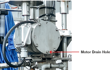
Fig. 3.3 – 1 – Motor drain hole

Fig. 3.3 – 1 – 1/2 HP Motor wiring – across the line start & run