7. Recommended Spare Parts #
Below is a list of recommended spare parts to keep in stock, as they may require replacement during normal system operation. For parts ordering, please contact partsales@innovateITcarwash.com.
For a complete reference of all system components, see Appendix 1 – System Identification, which includes a detailed parts diagram.
7.1 Replacing Foaming Regulator #
The following tools are needed to complete this task:
- 9/16” Wrench
- Turn off electrical supply to the unit.
- Turn off the main air supply to the unit.
- Open the regulator fully to vent all air out of the line.
- Disconnect the two poly tube lines at the rear of the regulator (Fig. 7.1 – 1).
- Solenoid to regulator
- Regulator to foaming output
- Unthread the capture nut on the regulator (Fig. 7.1 – 2).
- Remove regulator.
- Remove the elbows from the rear of the regulator
- Reinstall elbows into the rear of the new regulator.
- Install the new regulator on the panel with the new capture nut.
- Reconnect the two poly lines listed in step 4.
- Turn on the main air supply.
- Turn on the electrical supply to the unit.
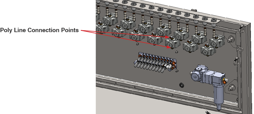
Fig. 7.1 – 1 – Foaming regulator poly line connection points
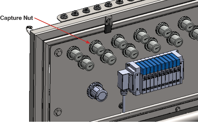
Fig. 7.1 – 2 – Regulator capture nut location
7.2 Replacing Process Air Valve #
The following tools are needed to complete this task:
- 1 1/16” Wrench
- 15/16” Wrench
- 9/16” Wrench
- Turn off the main air supply to the unit.
- Close the ball valve on the selected function (Fig. 7.2 – 1).
- Disconnect the quick connect fitting.
- Disconnect the air line to the valve.
- Disconnect the valve at the swivel fitting.
- Remove the hex nipple, quick connect, and the two air fittings from the head of the valve.
- Replace the hex nipple, quick connect, and the two air fittings on the new valve.
- Reinstall into the swivel fitting.
- Reinstall the injector kit.
- Reconnect the air line to the valve.
- Open the ball valve on the selected function.
- Turn on the main air supply.
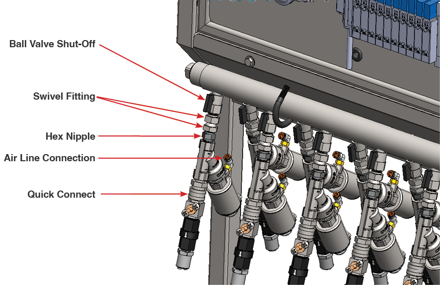
Fig. 7.2 – 1 – Process air valve replacement
7.3 Replacing Water Check Valve #
The following tools are needed to complete this task:
- 2 Adjustable Wrenches
- Close the ball valve to the function.
- Disconnect output line from the poly tube fitting.
- Remove quick connect from valve.
- Unthread the check valve from the injector (Fig. 7.3 – 1, following page).
- Confirm the orientation of the arrow on the check valve.
- Replace poly tube fitting onto the new check valve.
- Reinstall the push connect onto the injector.
- Reconnect poly tube.
- Open the ball valve.
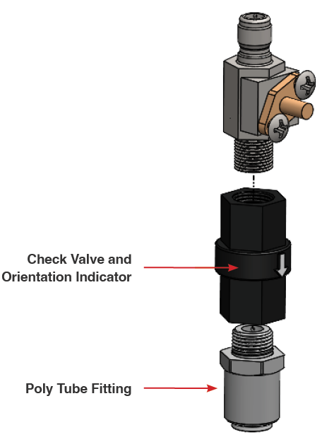
Fig. 7.3 – 1 – Check valve replacement
7.4 Replacing Metering Tip #
- Disconnect poly tube.
- Unscrew metering tip (Fig. 7.4 – 1).
- Install new tip.
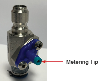
Fig. 7.4 – 1 – Metering tip replacement
7.5 Replacing Air Solenoid Card #
- Turn off the main air supply to the unit.
- Remove the two screws from the desired card (Fig. 7.5 – 1).
- Carefully remove the card from the manifold.
- Install the new card.
- Tighten the two screws.
- Turn on the main air supply.
- Check for leaks.
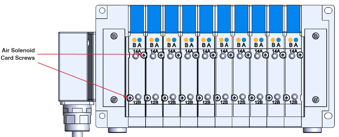
Fig. 7.5 – 1 – Air solenoid card replacement
7.6 Replacing Relay #
- Turn off electrical supply to the unit.
- Slide orange retaining tab to the left (Fig. 7.6 – 1).
- Remove existing relay module.
- Insert replacement relay. Press firmly until orange tab locks the relay into the place.
- Turn on the electrical supply to the unit and verify the relay is operational.
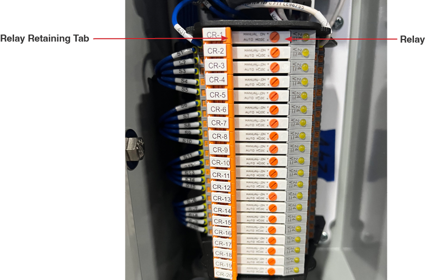
Fig. 7.6 – 1 – Relay replacement