4. Startup & Operation #
!WARNING! Check and verify the tightness of all power distribution lines (screw terminals) before the startup process.
NOTE: Ensure all steps and precautions in Section 3 have been completed before starting up the dispenseIT.
4.1 Priming The Pump #
- Turn on utility power from the wash to the dispenseIT system.
- Close the pump isolating valve(s) and open the priming plug located on the on the pump head on the front side of the pump (Fig. 4.1 – 1).
- Gradually open the isolating valve in the suction line until a steady stream of airless water runs out of the priming hole.
- Close the plug and tighten securely.
- Completely open the isolating valves.

Fig. 4.1 – 1 – Position of pump plugs
4.1.1 Split Manifold Capability (Optional) #
NOTE: If your system includes a split manifold, you must perform the steps listed in Section 4.1 – Priming the Pump and all subsequent pump steps for each individual pump. Ensure each side of the system isproperly primed and ready before continuing setup.
If your dispenseIT system is equipped with the optional split manifold, you gain the flexibility to operate multiple water configurations simultaneously. This setup allows you to:
- Run different water pressures
- Utilize varied water temperatures
- Draw from multiple water sources
The split manifold also adds system redundancy, helping keep your wash operational even if one side requires maintenance or troubleshooting.
The operating mode of the Split Manifold dispenseIT depends on two key settings:
- Ball valve position
- Selector switch position
These components are shown in Figure 4.1.1 – 1.

Fig. 4.1.1 – 1 – Split manifold layout
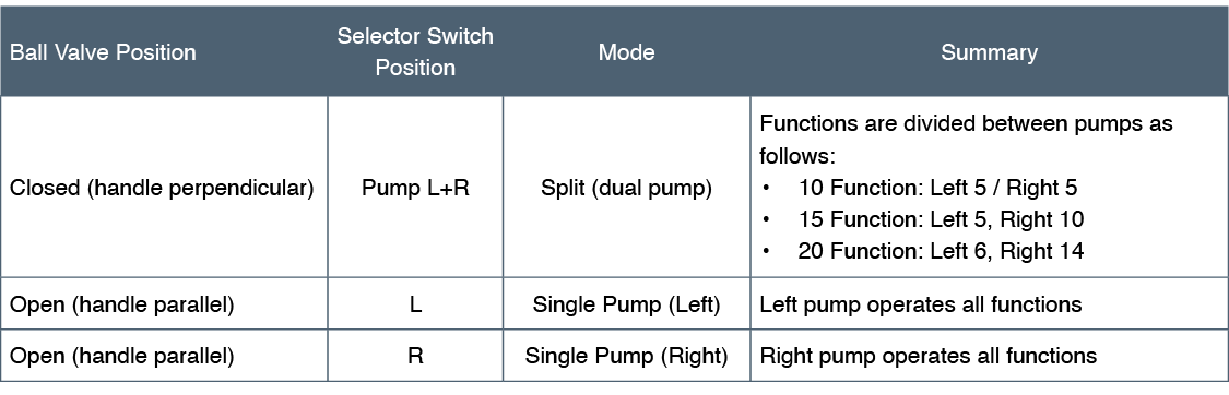
Refer to Table 4.1.1 – 1 to determine the correct mode of operation based on your current valve and switch settings. This chart outlines how different combinations of valve and switch positions affect system behavior—whether operating one pump or both.
Table 4.1.1 – 1 – Split Manifold operating modes
4.2 Starting The Pump #
- Verify that the electrical connections are in accordance with the wiring diagram on the motor.
- Turn on utility power from the wash to the dispenseIT system.
- Switch on the power and observe the direction of rotation.
- When viewed from above, the pump should rotate counterclockwise.
- To reverse the direction of rotation, first switch off the power supply. Interchange any two phases of the power supply.
- Switch on the power again and check for proper direction of rotation. Once direction of rotation has been verified, switch off the power again.
4.3 Pump Settings #
The Grundfos Pump arrives pre-programmed. For additional pump settings and pump programming instructions, refer to Appendix 3 – Pump Programming.
4.4 Verifying System Pressure #
- Verify that the system pressure on the dispenseIT pressure gauge and on the pump’s display screen match (min 100 psi – max 200 psi) (Fig. 4.4 – 1). To adjust system pressure, refer to Appendix 3.
- Check the system for leaks.
- While the pump is running, prime the pump a final time.
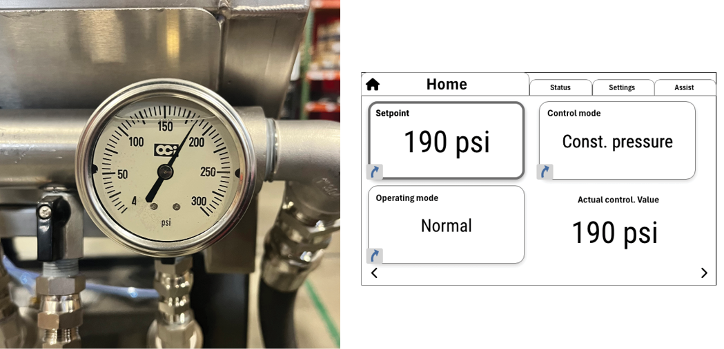
Fig. 4.4 – 1 – dispenseIT pressure gauge and pump home screen display
4.5 Verifying System Functions #
- Open the electrical enclosure and locate the orange rotary dial on CR 1-20 (Fig. 4.5 – 1).
- Turn the CR1 rotary dial to ‘Manual On’.
- Confirm that the corresponding solenoid indicator light illuminates on the Air Control Manifold.
- Both the liquid and air solenoid should open.
- Check for leaks at the poly tube connections.
- The function will remain on as long as it is set to ‘Manual On’.
- Once you’ve confirmed the function is operational, return the rotary dial to ‘Auto Mode’.
- Repeat the process with all remaining functions.
- If the corresponding solenoid indicator light doesn’t illuminate, refer to the Valves/Solenoids section within Section 6 -Troubleshooting for further guidance.
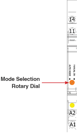
Fig. 4.5 – 1 – Rotary dial for manual testing of functions
4.5.1 Setting Foaming Functions #
To effectively set up and adjust the foaming functions on the dispenseIT, use the air regulator knob to control the foam density and texture (Fig. 4.5.1 – 1).
- Increase Foam Thickness:
- If a thicker or denser foam is desired, increase the air supply to the mixture.
- To do this, pull the air regulator knob and turn clockwise. This adjustment allows more air into the system, increasing foam density.
- Decrease Foam Thickness:
- For a thinner or less dense foam, reduce the air supply.
- Pull the air regulator knob and turn counter-clockwise. This reduces air in the mixture, resulting in a lighter application.
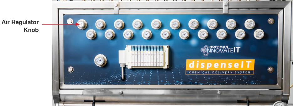
Fig. 4.5.1 – 1 – Air regulator knob