7. Recommended Spare Parts #
Below is a list of recommended spare parts that may require replacement during the course of system operation.
| innovateIT Product Number | Description |
|---|---|
| DS-REG-4-SMC | Foaming Regulator |
| 7303664 | Process Air Valve |
| DS-CV0074 | Standard Flow Injector Check Valve |
| DS-CV0072 | High Flow Injector Check Valve |
| 7903683 | Standard Metering Tips |
| 7903684 | High Flow Metering Tips |
#
7.1 Spare Part Replacement #
#
7.1.1 Replacing Foaming Regulator #
The following tools are needed to complete this task:
- 9/16” Wrench
- Turn off electrical supply to the unit.
- Turn off the main air supply to the unit.
- Open the regulator fully to vent all air out of the line.
- Disconnect the three poly tube lines at the rear of the regulator:
- Solenoid to regulator
- Regulator to valve
- Regulator to foaming output
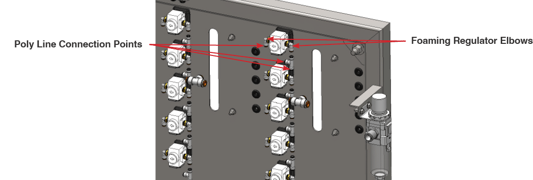
Fig. 7.1.1 – 1 – Foaming regulator poly line connection points
- Remove the elbows from the rear of the regulator (Fig. 7.1.1 – 1).
- Unthread the capture nut on the regulator (Fig. 7.1.1 – 2).
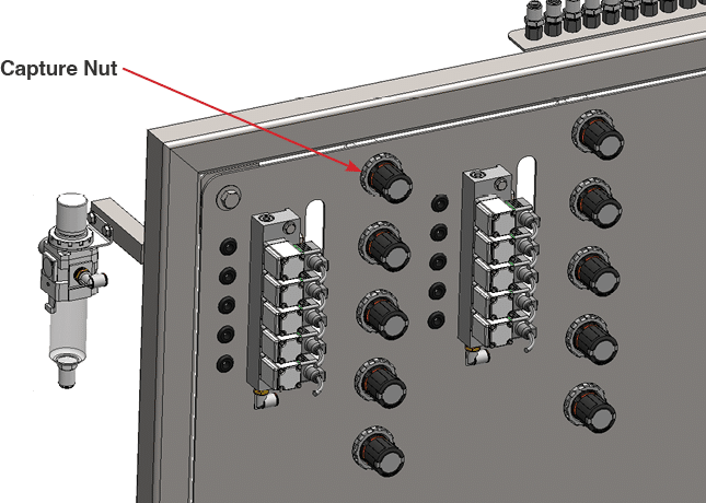
Fig. 7.1.1 – 2 – Regulator capture nut location
- Remove the regulator.
- Reinstall the elbows into the rear of the new regulator.
- Install the new regulator on the panel with the new capture nut.
- Reconnect the three poly lines.
- Turn on the main air supply.
- Turn on the electrical supply to the unit.
7.1.2 Replacing Process Air Valve #
The following tools are needed to complete this task:
- 1 1/16” Wrench
- 15/16” Wrench
- 9/16” Wrench
- Turn off the main air supply to the unit.
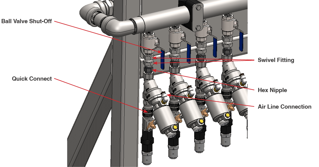
- Close the ball valve on the selected function (Fig. 7.1.2 – 1).
- Disconnect the quick connect fitting or unthread the high flow adapter depending on the type of function.
- Disconnect the air line to the valve.
- Disconnect the valve at the swivel fitting.
- Remove the hex nipple and the two air fittings from the head of the valve.
- Replace the hex nipple and the two air fittings on the new valve.
- Reinstall into the swivel fitting.
- Reinstall the injector kit.
- Reconnect the air line to the valve.
- Open the ball valve on the selected function.
- Turn on the main air supply.
Fig. 7.1.2 – 1 – Process air valve replacement
7.1.3 Replacing Check Valve #
The following tools are needed to complete this task:
- 2 Adjustable Wrenches
- Close the ball valve to the function.
- Disconnect output line from the poly tube fitting.
- Unthread the check valve from the injector (Fig. 7.1.3 – 1).
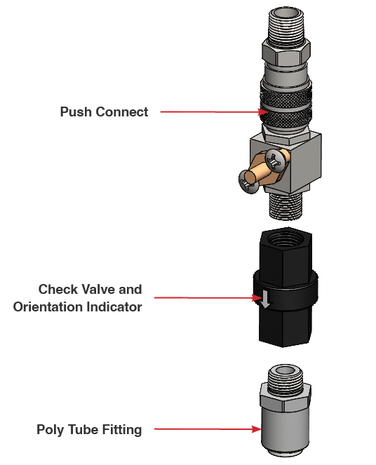
Fig. 7.1.3 – 1 – Check valve replacement
- Replace the poly tube fitting onto the new check valve.
- Reinstall the push connect onto the injector.
- Confirm the orientation of the arrow on the check valve.
- Reconnect poly tube.
- Open the ball valve.
7.1.4 Replacing Metering Tip #
- Disconnect poly tube.
- Unscrew metering tip (Fig. 7.1.4 – 1).
- Install new tip.
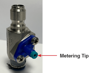
Fig. 7.1.3 – 1 – Metering tip replacement

