4. Startup & Operation #
WARNING: Check and verify the tightness of all power distribution lines (screw terminals) before the startup process.
NOTE: Ensure all steps and precautions in Section 3 have been completed before starting up the dispenseIT.
4.1 Priming The Pump #
- Turn on utility power from the wash to the dispenseIT system.
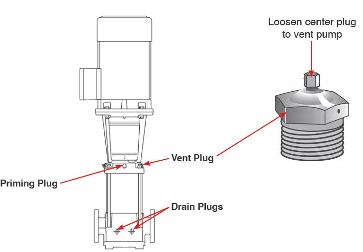
- Close the pump isolating valve(s) and open the priming plug on the pump head.
- Gradually open the isolating valve in the suction line until a steady stream of airless water runs out of the priming hole.
- Close the plug and tighten securely.
- Completely open the isolating valves.

Fig. 4.1 – 1 – Position of pump plugs
- Verify that the electrical connections are in accordance with the wiring diagram on the motor.
- Turn on utility power from the wash to the dispenseIT system.
- Switch on the power and observe the direction of rotation.
- When viewed from above, the pump should rotate counterclockwise.
- To reverse the direction of rotation, first switch off the power supply. Interchange any two phases of the power supply.
- Switch on the power again and check for proper direction of rotation. Once the direction of rotation has been verified, switch off the power again.
4.2 Pump Settings #
The Grundfos Pump arrives pre-programmed. For additional pump settings and pump programming instructions, refer to Appendix 3 – Pump Programming.
4.3 Verifying System Pressure #
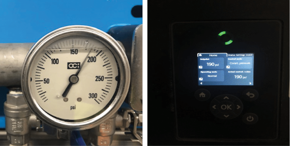
- Verify that the system pressure on the dispenseIT pressure gauge and on the pump’s display screen match (minimum 100 psi – maximum 200 psi) (Fig. 4.3. – 1). To adjust system pressure, refer to Appendix 3.
- Check the system for leaks.

Fig. 4.3 – 1 – dispenseIT pressure gauge and pump home screen display
4.4 Verifying System Functions #
- Override each function in your tunnel controller one at a time to ensure that the pump turns on with each function. Both the liquid and air solenoid should open.
- Check for leaks at the poly tube connections.
- Confirm each solenoid din coil LED illuminates when the solenoid is energized.
4.4.1 Setting Foaming Functions #
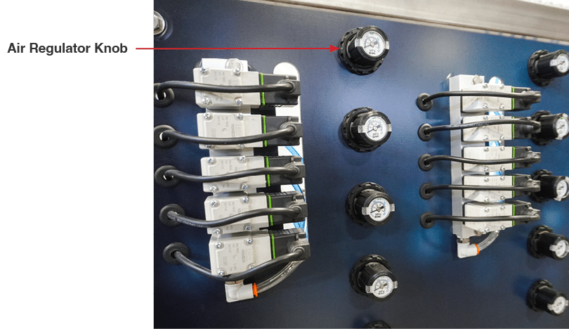
To effectively set up and adjust the foaming functions on the dispenseIT, use the air regulator knob to control the foam density and texture (Fig. 4.4.1 – 1).
- Increase Foam Thickness:
- If a thicker or denser foam is desired, increase the air supply to the mixture.
- To do this, turn the air regulator knob clockwise. This adjustment allows more air into the system, increasing foam density.
- Decrease Foam Thickness:
- For a thinner or less dense foam, reduce the air supply.
- Turn the air regulator knob counter-clockwise. This reduces air in the mixture, resulting in a lighter application.
It is necessary to set the regulators on non-foaming applicator lines at 2-5 psi in order to exhaust air from the process valves so that they can close fully. Refer to Section 6 – Troubleshooting if any of the following issues occur:
- Injector is not drawing any chemical.
- Injector draws the chemical for only a brief moment.
- Injector has a low but consistent vacuum chemical draw.

Fig. 4.4.1 – 1 – Air regulator knob
