7. Spare Parts #
Below is a list of recommended spare parts that may require replacement during the course of system operation.
7.1 Recommended Spare Parts #
RO-MBRN-440I – RO Membrane
RO-CBF-CAT-01230065 – 3 Micron Carbon Filter
RO-HSNG-80S30-1 – Membrane Housing
RO-HS-11/2BKFRNTR200RL – Hose Clamps – 1.5″ Hose
7.2 Spare Part Replacement #
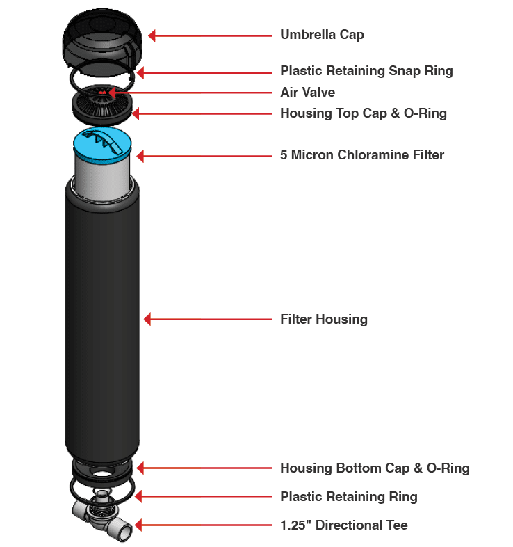
Carbon Filter (see Fig. 7.2 – 1)
- Before starting, close the ball valve from your municipal feed water supply line.
- Turn 480VAC Main Disconnect switch on the front of the electrical enclosure to the OFF position.
- Verify the feed pressure is 0 psi.
- Press down the red air valve on the top of the carbon filter housing cover to bleed air out of the system.
- Carefully remove the snap ring from the cover of the filter housing and remove the cap.
- Remove the filter using the tabs at the top of the filter.
- Apply a generous coating of silicone grease to the two o-rings at the bottom of the new filter.
- Insert the new filter into the housing.
- Apply a generous coating of silicone grease to the filter cover and reinsert into the housing.
- Reinstall the snap ring starting with the tail and working around to the peg and ensure it is fully seated.
- Turn 480VAC Main Disconnect switch on the front of the electrical enclosure to the ON position.
- Crack open your municipal water supply line ball valve.
- Slowly open the line to allow water to flow back into the system.
- Refer to Section 4 – Startup & Operation of the RO System manual for instructions on filling and purging the RO System before bringing it back online.

Fig. 7.2 – 1 – Carbon block components
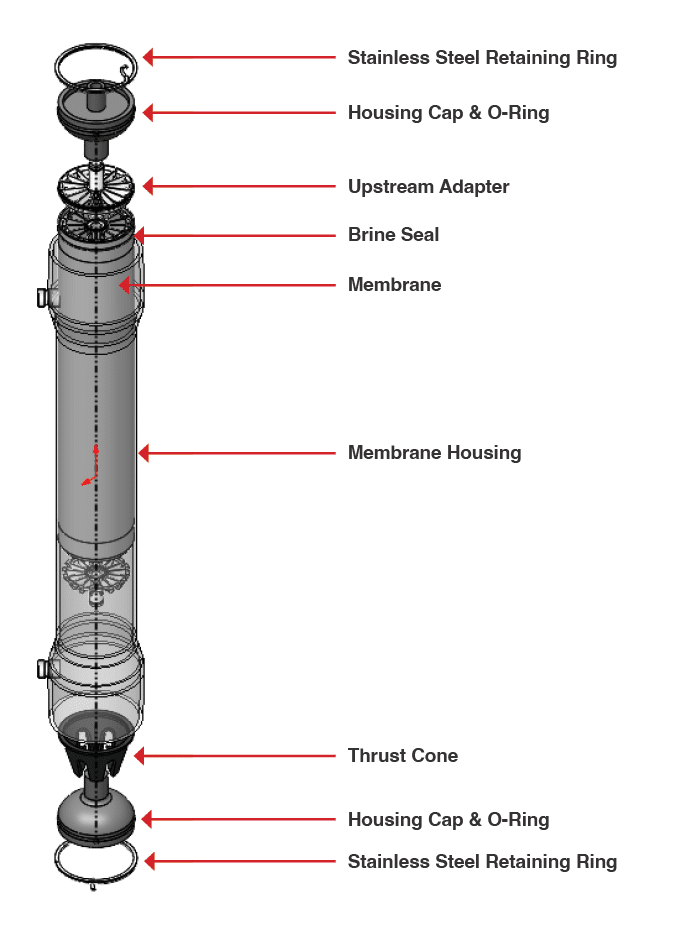
RO MEMBRANE (see Fig. 7.2 – 2)
- Inspect all seals prior to installation and ensure there are no nicks or tears.
- Turn 480VAC Main Disconnect switch on the front of the electrical enclosure to the OFF position.
- Verify the feed pressure is 0 psi.
- Open the lower membrane ball valve to drain the membrane housing.
- Disconnect the flow switch sensor cable.
- Remove the split clamps from the top manifold.
- Remove the top manifold from the top of the membrane.
- Remove the spiral snap ring.
- Remove the plumbing from the top of the membrane cap.
- Rotate the membrane cap counterclockwise and remove it from the top of the membrane.
- Thread four heavy duty zip ties through the openings and the top of the membrane to create handles.
- Using the handles, remove the membrane from the housing.
- Apply a generous coating of silicone grease to the O-ring on the lower cap of the new membrane.
- Attach the membrane cap to the bottom of the new membrane.
- The feed water flow runs from the top to the bottom of the membrane housings.
NOTE – The membrane brine seal (black seal at one end of the membrane must be located at the feed port end (top port) to ensure proper flow of feed water through the membrane.
- Apply a generous coating of silicone grease to the brine seal on the opposite end of the membrane
- Thread four heavy duty zip ties through the openings to create handles.
- Using the handles, insert the membrane into the housing from the top opening.
NOTE – Take extra care when lowering the new membrane into the housing. Do not drop it or press down with too great of a force. Ensure O-rings are not damaged during insertion, as this will cause untreated water to leak into the permeate.
- If the membrane is seated correctly, there should be approximately 9.5” from the top of the membrane to the top of the housing.
- Install the top membrane cap and ensure is locked into place.
- Apply a generous coating of silicone grease to the membrane’s top plumbing and attach it to the membrane cap.
- Reinstall the spiral snap, ring, and ensure it is fully seated.
- Reattach the top manifold and split clamps.
- Reconnect the flow switch sensor cable.
- Close the membrane ball valve.
- Turn 480VAC Main Disconnect switch on the front of the electrical enclosure to the ON position.
- Crack open your municipal water supply line ball valve.
- Slowly open the line to allow water to flow back into the system.
- Refer to Section 4 – Startup & Operation of the RO System manual for instructions on filling and purging the RO System before bringing it back online.
NOTE – New membranes are installed dry. It will take a few hours of operation for the manufacturing chemicals to flush off the surfaces of the membrane and the RO TDS to drop below 20. After replacing a membrane, the initial RO production should be dumped to the drain until the TDS of the water is at normal operating levels. 
Fig. 7.2 – 2 – Membrane components
