2. System Overview #
Reverse Osmosis Spot-Free Rinse Systems address the need for pure, mineral-free water to enhance the wash process’s efficiency and effectiveness. This system directly contributes to maintaining consistent water quality, reducing maintenance needs, and optimizing operational costs by mitigating the adverse effects of hard water on both the vehicles being washed and the car wash equipment itself.
Municipal water contains a variety of dissolved minerals, such as calcium, magnesium, and sodium, which contribute to water hardness and can leave spots and residues on vehicles after drying. An RO System filters these minerals out, producing pure water (permeate) that results in a spot-free rinse.
The quality of municipal water can also vary significantly due to seasonal changes, local water treatment variations, and infrastructure quality. An RO system ensures that the rinse water quality is consistently high, irrespective of the incoming water’s condition, by removing up to 99% of dissolved solids and impurities.
The use of this high-quality RO water can also reduce chemical usage and extend the life of car wash equipment. Since the water is purer, it is more effective at rinsing away soap and residues, which can lead to a reduction in chemical costs. Additionally, the pure water without minerals prevents the buildup of scale and corrosion in pipes and nozzles, reducing maintenance requirements and extending the operational lifespan of the equipment.
2.1 Features & Functions #
innovateIT Car Wash Equipment LLC has developed a high-efficiency Reverse Osmosis Spot-Free Rinse System to provide spot-free rinse service for express car wash applications.
The system uses a ‘Flow on Demand’ control algorithm to adjust pressure on the membranes by varying pump speed, which automatically generates the required RO for the demand of the car wash. This allows the pump to operate at lower pressures for longer periods, increasing membrane life and reducing pump cycling. Additionally, it avoids short cycling the pump, ensuring the unit runs efficiently even during periods of low or intermittent car wash tunnel volume.
This approach produces high-quality spot-free rinse water with maximum operating efficiency. It also allows for the use of a reduced-size RO storage tank which is fully integrated into the RO stainless steel stand. The integrated system eliminates the cost of buying and installing large buffer storage tanks needed to meet the high-volume tunnel demand at busy washes.
The tank level sensor (pressure transducer) generates the request for the RO production flow rate, which varies based upon the RO storage tank level.
In addition, the Grundfos VFD pump allows the unit to produce a minimum flow of 10 GPM for Standard Flow units and 15 GPM for High Flow units at 40F feed water temperature to ensure consistent flow for the wash even in extremely cold winter climates. Figure 2.1 – 1 shows the range of permeate flow that the RO System produces over a range of feedwater temperature.
The RO System utilizes fixed orifices on the recirculation and reject lines to provide a 60/40 split of recirculation to reject flow, maximizing fresh water usage.
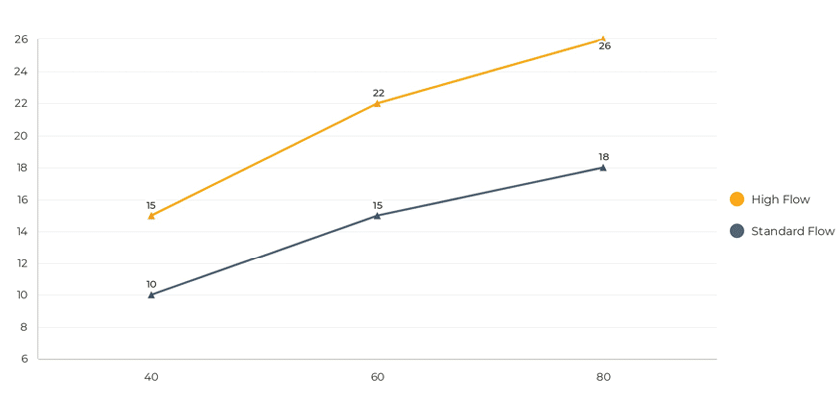
Fig. 2.1 – 1 – Permeate flow based on feed temperature
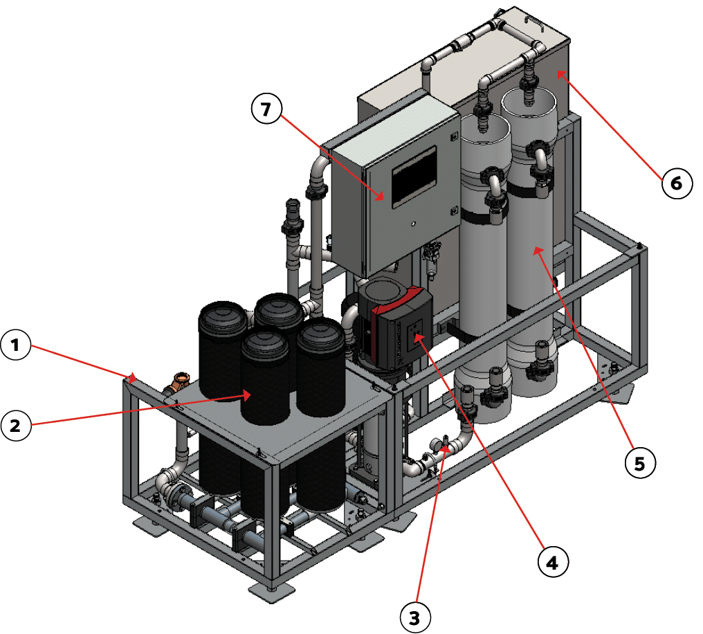
Fig. 2.1 – 2a – RO System identification
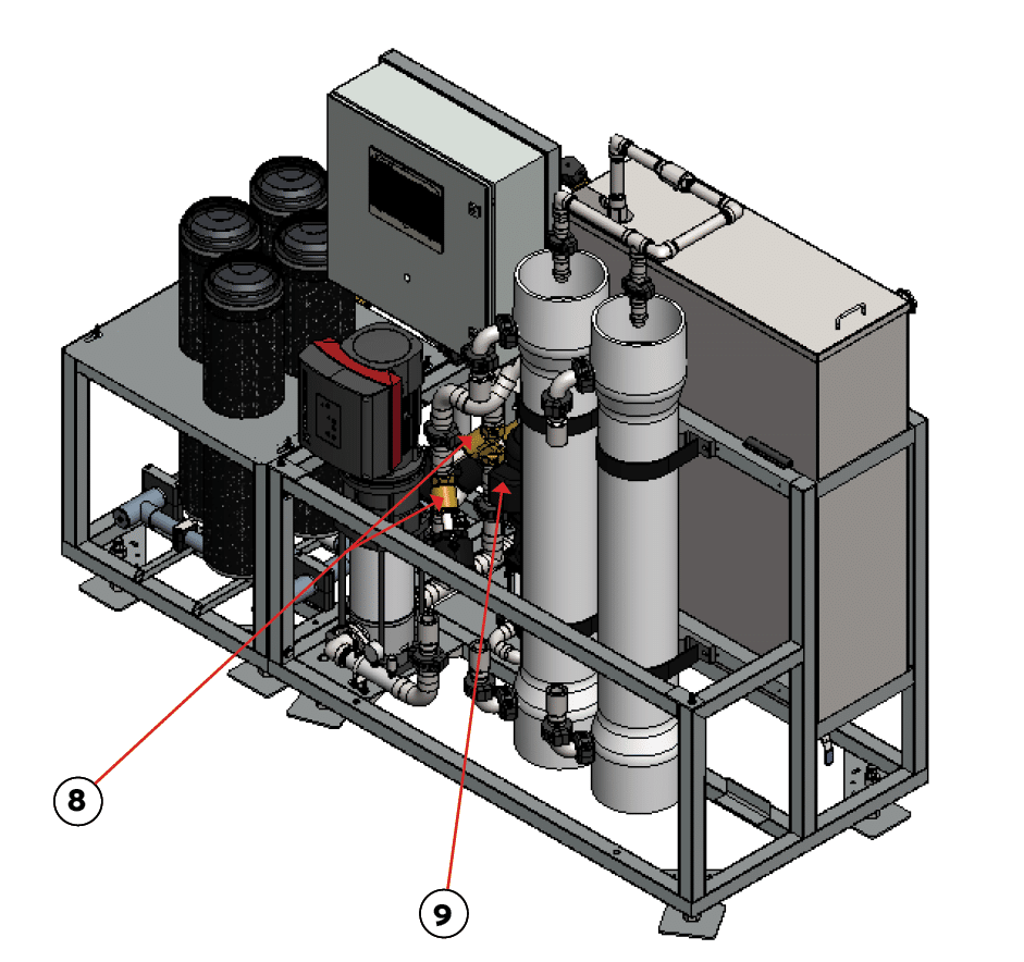
Fig. 2.1 – 2b – RO System identification
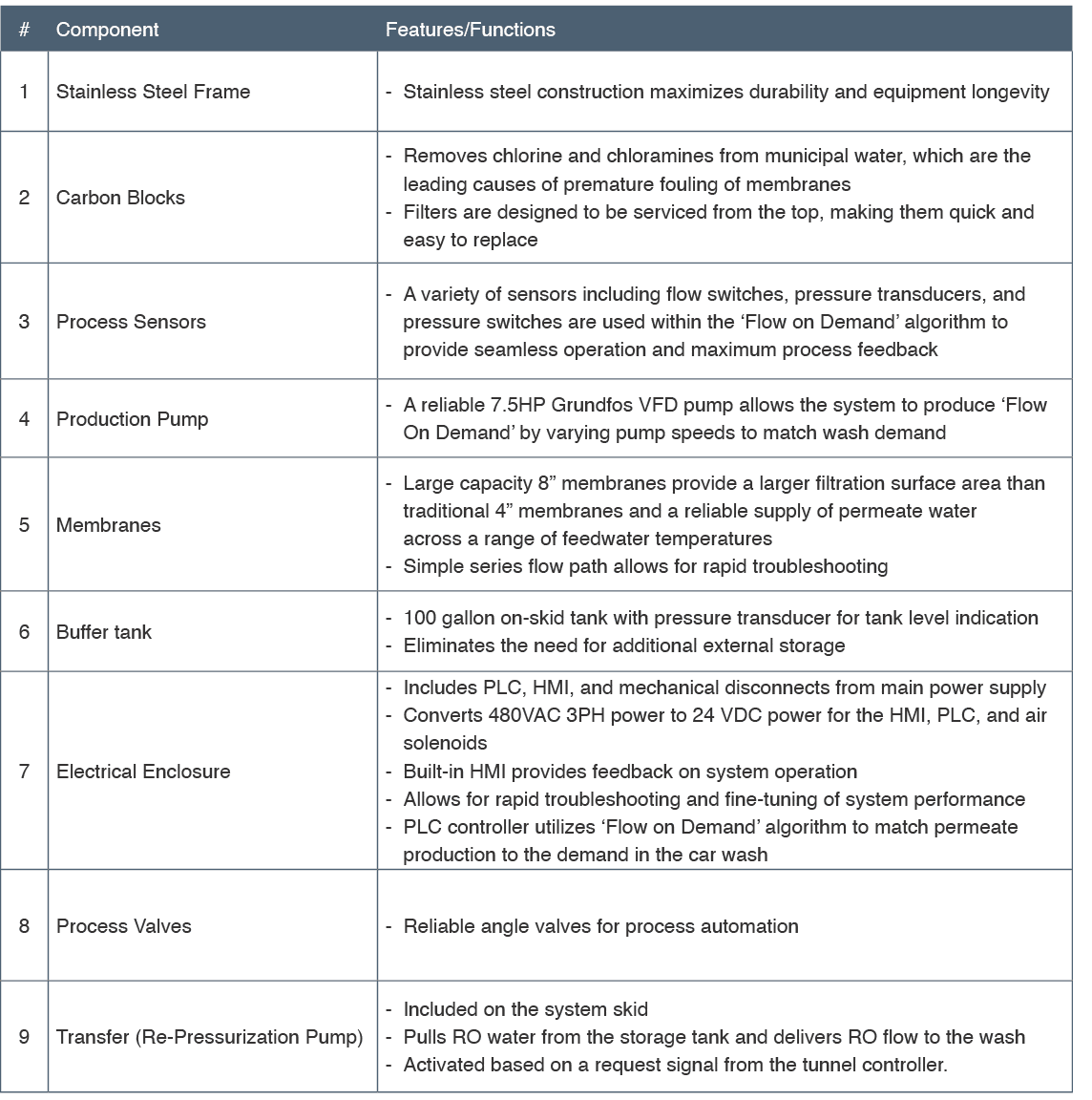
Table 2.1 – 1 – RO System component features and functions
2.2 System Specifications #
Table 2.2 – 1 – RO System specifications
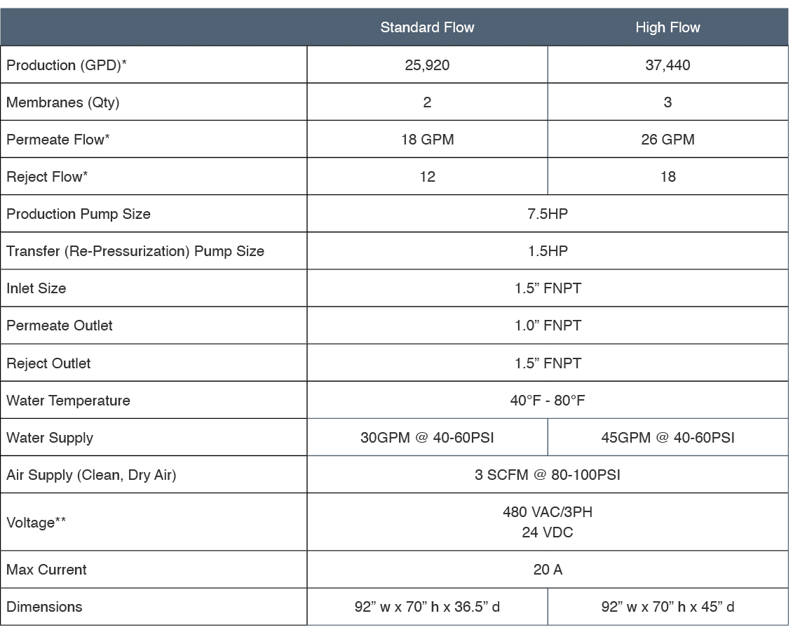
* Production rates based upon the supply of 77F softened water
** 480 VAC 3PH power with ground from the facility. Review the electrical schematic for required current ratings and integration of the system controller. The primary RO Production Pump is 7.5 HP, and the Transfer (Re-Pressurization) Pump is 1.5 HP. RO Power requirement is 20A, 3 Phase 480VAC fed by a trip class 10 or higher. Wiring and conduits as allowed by local code and NEC-70.
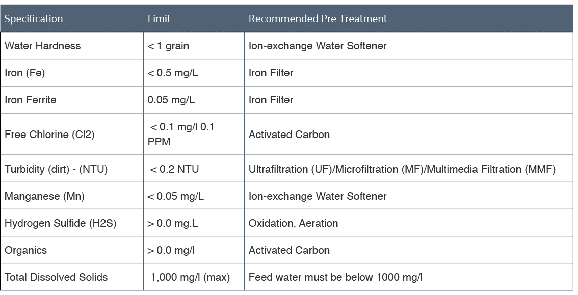
NOTE – Failure to properly pre-treat the water may result in reduced membrane life and premature membrane failure and is not covered under the limited warranty.
Table 2.2 – 2 – Feed water limits and recommended pre-treatment approach