Appendix 3 – Parts & Service Notes #
Physical Parameters
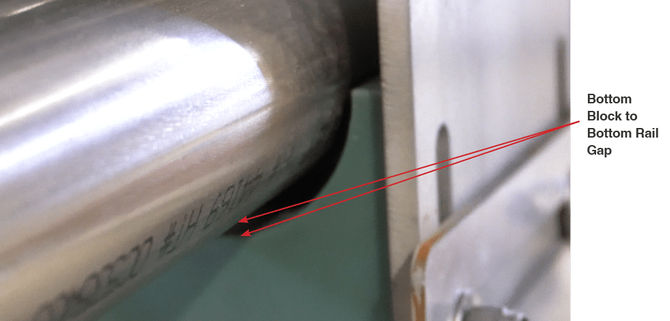
Bottom Block to Bottom Rail: 3/32” Gap #
A 3/32” gap is recommended between the bottom block and bottom rail for trolley stabilization. The bottom block stabilizes the trolley by minimizing tilting side to side and rocking back and forth. An unstable trolley is more likely to result in top or bottom blocks binding while sliding along the rails, spur gear jamming on the toothed rack, and increased belt wear.
- Tools: Two 9/16” wrenches, one 3/32” diameter probe longer than the bottom block, a hammer.
Adjusting Bottom Block Gap
Tools: Two 9/16” wrenches, one 3/32” diameter probe longer than the bottom block, a hammer.
NOTE: Adjusting the spur gear gap is much easier and quicker when the bottom block has the correct gap.
- With two 9/16” wrenches, loosen the two nuts of the bottom block until block can be moved down with a gentle hammer tap.
- Insert the probe at the lowest point between the bottom block and the bottom rail. The probe must extend past both ends of the block.
- Raise the bottom block until snug against the probe at both ends. If tapping block up with a hammer, the tapping sound will change to a deeper tone when block is snug against the probe.
- Tighten the 9/16” nuts while ensuring the block is snug against the probe at both ends of the block.
- Remove the probe and, as a rule-of-thumb technique, see if the trolley flag looks level to confirm the bottom block is level.

Fig. 1 – Bottom block to bottom rail gap
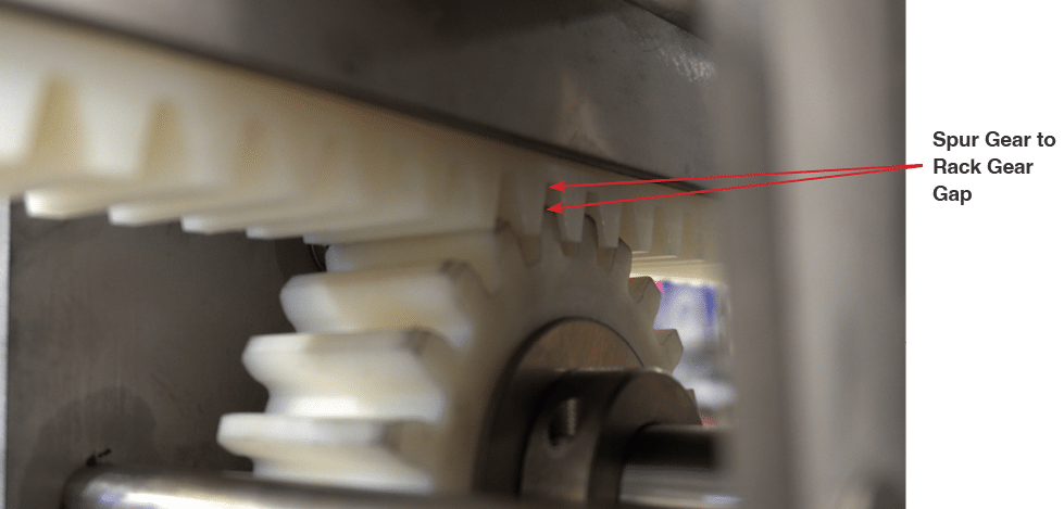
Spur Gear to Rack Gear: 3/32” Gap #
The spur gear engages and turns the water shaft when the trolley moves forward to towards the exit bumper.
The gap between the spur gear and rack gear must not be so tight as to add excess resistance to trolley movement but not so loose as to intermittently misalign gear teeth and block trolley movement.
Adjusting Spur Gear Gap
Tools: Two 9/16” wrenches, one 3/32” diameter probe with 1.5” of one end bent at a right angle.
NOTE: A correct gap of 3/32” between the bottom block and the bottom rail will help when adjusting the spur gear gap because, when lifting the spur gear, the entire trolley will be limited by the bottom block gap. Check this gap the entire length of travel.
- Loosen the four nuts securing the two plastic flanged shaft bearing assemblies to the trolley side plates.
- Lower the spur gear slightly and rest the short bent end of the 3/32” probe between the two uppermost teeth of the spur gear.
- Lift spur gear until probe is held snug, pressed down by a tooth of the toothed rack.
- Re-tighten the 9/16” nuts, leaving the probe end between the teeth.
- Manually pull the trolley belts to roll over the probe a couple of times.
- A correct gap is indicated by feeling the trolley gently “bumping” as it moves past the point where the probe-filled spur gear teeth meets the toothed rack.
- Too small of a gap is indicated by a trolley difficult to pull past that point.
- Remove probe and double check all four 9/16” nuts are secure.

Fig. 2 – Spur gear to rack gear gap
Belt Deflection: 1.25” #
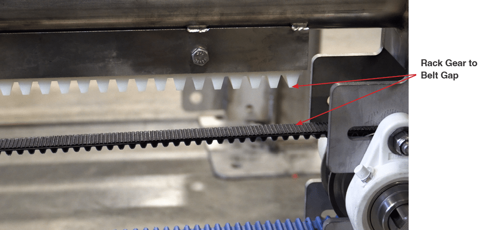
A belt deflection of 1.25” is recommended. Belt tension is measured by the amount a belt deflects from a line drawn between the two uppermost or two lowermost locations where the belt is in contact with the pulleys.
Consistency in how belt deflection is measured is critical when the same or different repair personnel may work on the wheelblastIT at different times.
The belt turns around drive and idler pulleys to pull the trolley back and forth along the rails. If there is too much tension on the belt, the belt motor will need increased amperage to turn and a VFD may exceed the amperage safety limit. If the belt is too loose, the drive pulley may skip belt teeth, leading to variable trolley forward travel distances and poor cleaning performance.
Measuring Belt Deflection
Tools: Two 9/16” wrenches, ruler or tape measure, a hammer.
The following steps are recommended to ensure consistency, accuracy, and simplicity when measuring belt deflection:
- Push the trolley past the ‘Home’ position to the bumper at the entrance side of the rails.
- At the exit end of the rails, as close as possible to the idler pulley, measure the distance from the lowest point of the toothed rack to the top of the belt of the upper belt run.
- Add 1.25” to that measurement.
- At the mid-point between the idler pulley and the exit-side belt clamp, push down on the upper belt run until the lower belt run no longer rises up.
- The tension applied by pushing down readies the upper belt run deflection measurement for the purpose of this procedure.
- While maintaining downward tension on the upper belt run, at the mid-point between the idler pulley and the belt clamp, measure the distance from the lowest point of the rack gear to the top of the belt at the lowest point of the deflected upper belt run.
- If this measured belt deflection is not with a quarter inch (0.25”) of the measurement at the idler pulley plus 1.25”, then belt tension adjustment is required.

Fig. 3 – Rack gear to belt gap
Adjusting Belt Tension
- At the idler pulley, loosen the four 9/16” nuts on the two plastic flanged shaft bearing assemblies only enough that a gentle hammer tap will move the bearing slightly.
- Use the hammer to gently adjust the position of both bearing assemblies. Make sure the pulley shaft remains at a right angle (perpendicular) to the rails.
- Small adjustments will result in a large change in the belt deflection measurement.
- Remeasure the belt deflection and readjusting the position of the idler pulley shaft bearing assemblies, until the belt deflection is correct.
- Tighten all four of the 9/16” nuts on the bearing assemblies. Be sure not to over-tighten bolts and bend trolley side plates in towards each other.
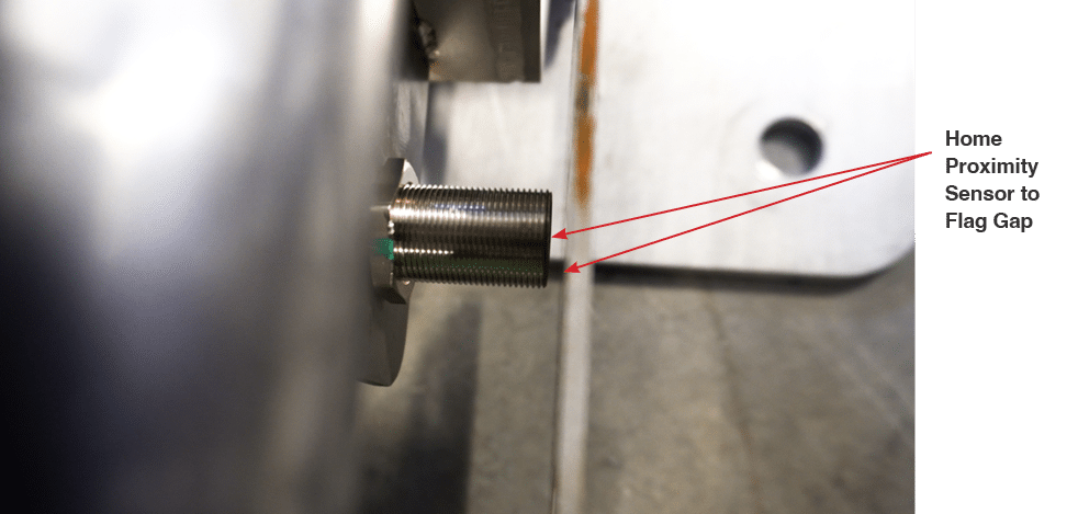
Home Proximity Sensor to Flag: 1/8” Gap Maximum #
A sensor to flag gap of 1/8” is recommended. The ‘Home’ proximity sensor detects when the trolley flag is in front of the sensor barrel.
If the gap is too small, the stiff metal flag may hit the sensor and stop the trolley from returning to the Home position. If the gap is too large, the sensor may not detect the flag and the trolley will no longer move forward.
The maximum distance the sensor will detect the flag is about 1/4”. However, at this distance, the trolley may be detected late in the reverse movement cycle and hit the entrance side bumper, ultimately resulting in inconsistent forward travel distances.
Measuring the Gap
Tools: Two 15/16” wrenches, possibly a 15/16” deep socket wrench, a 1/8” probe (can use 1/8” hex driver that is also used on plastic flanged shaft bearing set screws).
- Move the trolley until the flag covers the entire face of the sensor. If the 1/8” probe fits in between sensor and flag without extra space, then the gap is set correctly.
Adjusting The Gap/Repositioning The Sensor
- Reposition the sensor by moving the two jam nuts along the threaded barrel of the sensor.
- Create space to work in by pushing the trolley away from the ‘Home’ position.
- Unscrew the sensor cable from the back of the sensor to minimize chances of damaging the connection.
- Secure the wall-side jam nut with a 15/16” wrench and loosen the car-side jam nut with the other 15/16” wrench.
- With the jam nuts loose, turn the jam nuts up or down the sensor barrel until, when jam nuts are tightened, the face of the sensor is 1/8” from the flag when the trolley is in the ‘Home’ position.

Fig. 4 – Home proximity sensor to trolley flag gap
