7.1 Recommended Spare Parts #
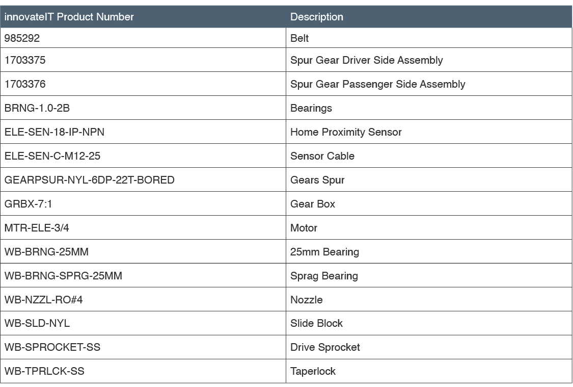
Below is a list of recommended spare parts that may require replacement during the course of system operation.
Table 7.1 – 1 – wheelblastIT spare parts list
7.2 Spare Part Replacement #
#
7.2.1 Replacing Belt #
The following tools are needed to complete this task:
- (2) 9/16” Wrench
- (2) 7/16” Wrench
- Ruler/Tape Measurer
- Rubber Mallet
- Turn Main Disconnect switch on the front of the electrical enclosure to the OFF position and ensure that all outputs from the tunnel controller to the control solenoids for the wheelblastIT are turned OFF.
- If wheelblastIT controls are integrated into sites tunnel controller, ensure all power (motor and control) to the wheelblastIT unit is turned OFF and all outputs to the control solenoids are turned OFF.
- At the idler pulley, loosen the four nuts on the two plastic flanged shaft bearing assemblies (Fig. 7.2.1 – 1).
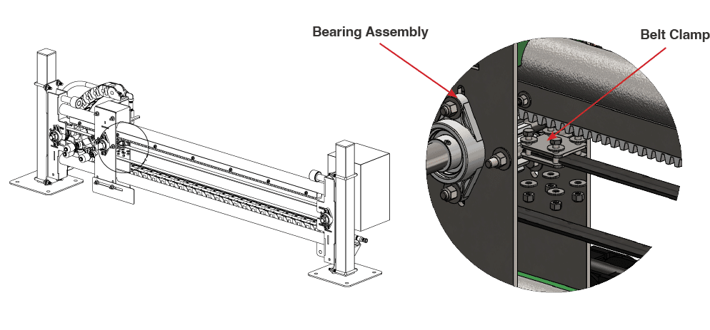
Fig. 7.2.1 – 1 – Belt removal
- Gently tap the bearing assemblies with a rubber mallet to reduce tension on the belt.
- Loosen the bolts on the belt clamps to release the belt.
- Slide the belt off the drive and idler pulleys and carefully remove the belt.
- Fully remove the belt clamps from the trolley (do not discard).
- Position the new belt over the drive and idler pulleys. Ensure the belt is properly seated on both pulleys.
- Place the ends of the belt into the belt clamps and tighten the bolts to secure the belt.
- Ensure the grooves of the belt are aligned with the slots in the lower plate of the belt clamp.
- Reinstall the belt clamps to the trolley.
- At the idler pulley, gently tap the bearing assemblies with a hammer to adjust their position. Make sure the pulley shaft remains at a right angle (perpendicular) to the rails.
- Use a ruler or tape measure to check the belt deflection and follow the instructions in Appendix 3 – Parts & Service Notes to set the proper belt deflection (1.25”).
- Once the belt deflection is correct, tighten all four nuts on the bearing assemblies. Be sure not to overtighten bolts and bend trolley side plates in towards each other.
- Turn the Main Disconnect switch on the front of the electrical enclosure to the ON position (re-establish power to the wheelblastIT).
7.2.2 Replacing Spur Gear & Water Shaft Assembly #
The following tools are needed to complete this task:
- (2) 9/16” Wrench
- (2) 7/16” Wrench
- Pipe Wrench
- Turn Main Disconnect switch on the front of the electrical enclosure to the OFF position.
- If wheelblastIT controls are integrated into sites tunnel controller, ensure all power (motor and control) to the wheelblastIT unit is turned OFF and all outputs to the control solenoids are turned OFF.
- Loosen the bolts holding bearings at the end of the belt (Fig. 7.2.2 – 1). This will be the end opposite the motor (traditionally exit end of wash).
- Slide the bearings forward to relieve tension.
- Remove the bolts holding the belt clamps onto the trolley carriage (Fig. 7.2.2 – 1).
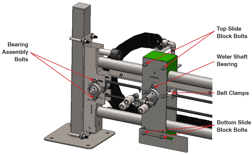
Fig. 7.2.2 – 1 – Bearings, slider block, and belt clamp bolt locations
- Remove the bolts holding the bottom slide block and trolley flag (Fig. 7.2.2 – 1).
- This will most likely cause the carriage to swing slightly. Blocking can be used under the carriage for support.
- Loosen the set screws on both the front (trident or car side) and rear (wall side) bearing holding the water shaft/trident (Fig. 7.2.2 – 2).
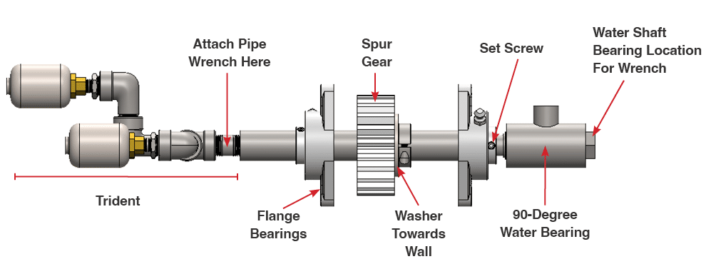
Fig. 7.2.2 – 2 – Water shaft assembly
- Loosen, but do not remove, the top slide block bolts (Fig., 7.2.2 – 1).
- Hold the trident end of the water shaft (ideally pipe wrench on the pipe nipple) and unthread the water shaft from the 90-degree water bearing on the wall side of the unit (Fig. 7.2.2 – 2).
- Do not hold onto water shaft directly as it still needs to pass through the bearing to be removed.
- Unthread the trident from the water shaft carefully to ensure the surface of the water shaft is not damaged.
- Remove the bearing on the front of the unit holding the water shaft (Fig. 7.2.2 – 1).
- Pull the water shaft out of the rear bearing and remove the assembly from trolley carriage.
- Insert the new assembly into the rear bearing in the same orientation as before.
- If installing a one-way bearing assembly, the washer on the spur gear should be towards wall.
- If installing a bearing-free assembly, the shaft collar should be towards wall.
- Reinstall the front bearing onto the water shaft and trolley carriage plate but keep the bolts loose on the plate.
- Thread the trident onto the new water shaft assembly.
- Thread the 90-degree water bearing onto water shaft assembly (Fig. 7.2.2. – 2).
- Do not hold onto the water shaft directly as it still needs to pass through the bearing to be removed.
- Adjust the spur gear to mesh with the gear rack and tighten flange bearings in place. Follow the instructions in Appendix 3 – Parts & Service Notes to properly mesh the spur gear and rack gear.
- Reinstall the bottom slider block and trolley flag
- Push up on the slider block to ensure proper fitting the of trolley carriage to the frame.
- Reinstall the belt clamps onto the trolley carriage.
- Tighten the upper slider block bolts.
- Tighten the set screws on the bearings holding the water shaft/spur gear assembly.
- Slide the bearings on and tighten the bolts holding the bearings.
- Use a ruler or tape measure to check the belt deflection and follow the instructions in Appendix 3 – Parts & Service Notes to set the proper belt deflection (1.25”).
- Follow the instructions in Appendix 3 – Parts & Service Notes to ensure the trolley flag is in proper position.
- Turn the Main Disconnect switch on the front of the electrical enclosure to the ON position (re-establish power to the wheelblastIT).
7.2.3 Replacing Home Proximity Sensor #
The following tools are needed to complete this task:
- (2) 15/16” Wrench
- 1/8” Spacer
- Turn the Main Disconnect switch on the front of the electrical enclosure to the OFF position and ensure that all outputs from the tunnel controller to the control solenoids for the wheelblastIT are turned OFF.
- If wheelblastIT controls are integrated into sites tunnel controller, ensure all power (motor and control) to the wheelblastIT unit is turned OFF and all outputs to the control solenoids are turned OFF.
- Move the trolley away from the Home position to create space for working.
- Unscrew the sensor cable from the back of the home proximity sensor to minimize the chances of damaging the connection (Fig. 7.2.3 – 1).
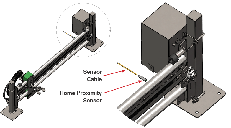
Fig. 7.2.3 – 1 – Home proximity sensor
- Loosen the jam nuts and unscrew the sensor completely from its mounting.
- Clean the sensor mounting area using a cleaning cloth.
- Using a jam nut, position the new sensor until the face of the sensor is approximately 1.5” from the face of the sensors mounting plate.
- Move the trolley until the flag covers the entire face of the sensor.
- Insert the 1/8” spacer between the sensor and the flag to check the gap. The spacer should fit without extra space.
- If the gap is not correct, adjust the position of the sensor by moving the jam nuts along the threaded barrel of the sensor until there is a gap of 1/8” between the sensor face and the flag.
- Tighten the jam nuts and ensure the sensor is securely mounted and the gap remains correct.
- Apply dielectric grease to the sensor connection.
- Screw the sensor cable back onto the new home proximity sensor, ensuring a secure connection.
- Turn the Main Disconnect switch on the front of the electrical enclosure to the ON position (re-establish power to the wheelblastIT).
- Move the trolley back until the flag covers the face of the sensor and verify the proximity sensor is functioning properly (See Section 4.3).
- Turn the Main Disconnect switch on the front of the electrical enclosure to the ON position (re-establish power to the wheelblastIT).
7.2.4 Replacing Slide Block #
The following tools are needed to complete this task:
- (2) 9/16” Wrench
- (2) 7/16” Wrench
- Turn the Main Disconnect switch on the front of the electrical enclosure to the OFF position and ensure that all outputs from the tunnel controller to the control solenoids for the wheelblastIT are turned OFF.
- If wheelblastIT controls are integrated into sites tunnel controller, ensure all power (motor and control) to the wheelblastIT unit is turned OFF and all outputs to the control solenoids are turned OFF.
- Position a block or support under the trolley so that it is fully supported.
- Loosen and remove the top two bolts securing the top slide block to the trolley (Fig. 7.2.4 – 1).
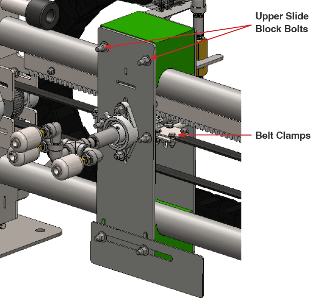
Fig. 7.2.4 – 1 – Replacing top slide block
- Loosen the belt clamp bolts and set screws on the car side nozzle shaft clamp on the trolley so that the two trolley plates are loose and the top slide block can be easily removed.
- Remove the top slide block.
- Clean the rail and surrounding area using a cleaning cloth. Remove any debris, old lubricant, or corrosion to ensure a smooth installation of the new slide block.
- Align the new slide block between the two trolley plates and with the rail and slide it into place. Ensure it is seated properly.
- Reinsert and tighten the mounting bolts to secure the new slide block on the rail. Ensure the block is firmly in place and properly aligned.
- Follow the instructions in Appendix 3 – Parts & Service Notes to reset the position of the bottom block to the bottom rail.
- Move the trolley back and forth by hand along the length of the rail to ensure smooth and consistent travel.
- Turn the Main Disconnect switch on the front of the electrical enclosure to the ON position (re-establish power to the wheelblastIT).
7.2.5 Replacing Belt Clamps #
The following tools are needed to complete this task:
- (2) 9/16” Wrench
- (2) 7/16” Wrench
- Turn Main Disconnect switch on the front of the electrical enclosure to the OFF position.
- If wheelblastIT controls are integrated into sites tunnel controller, ensure all power (motor and control) to the wheelblastIT unit is turned OFF and all outputs to the control solenoids are turned OFF.
- Loosen the bolts holding bearings at the end of the belt (Fig., 7.2.5 – 1). This will be the end opposite the motor (traditionally exit end of wash).
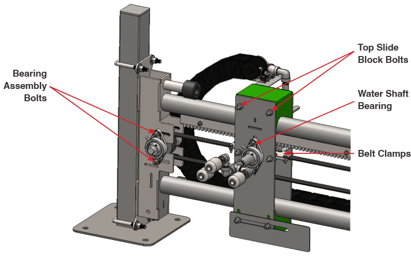
Fig. 7.2.5 – 1 – Replacing belt clamps
- Slide the bearings forward to relieve tension.
- Loosen the top slide block bolts.
- Remove the belt clamps from the carriage.
- Remove the 4 bolts holding the clamp together.
- Replace the belt clamp and reinstall onto belt
- Be sure to fit the cogs in the belt into the grooves in clamp.
- Reinstall the clamp onto the carriage.
- Tighten the top slider block bolts.
- Slide the bearings on and tighten the bolts holding the bearings.
- Use a ruler or tape measure to check the belt deflection and follow the instructions in Appendix 3 – Parts & Service Notes to set the proper belt deflection (1.25”).
- Follow the instructions in Appendix 3 – Parts & Service Notes to ensure the trolley flag is in proper position.
- Turn the Main Disconnect switch on the front of the electrical enclosure to the ON position (re-establish power to the wheelblastIT).
7.2.6 Replacing Drive Sprocket #
The following tools are needed to complete this task:
- (2) 9/16” Wrench
- 3/16” Hex Driver
- Turn the Main Disconnect switch on the front of the electrical enclosure to the OFF position and ensure that all outputs from the tunnel controller to the control solenoids for the wheelblastIT are turned OFF.
- If wheelblastIT controls are integrated into sites tunnel controller, ensure all power (motor and control) to the wheelblastIT unit is turned OFF and all outputs to the control solenoids are turned OFF.
- Remove the motor cover.
- Loosen the bolts holding bearings at the end of the belt (Fig. 7.2.6 – 1). This will be the end opposite the motor (traditionally exit end of wash).
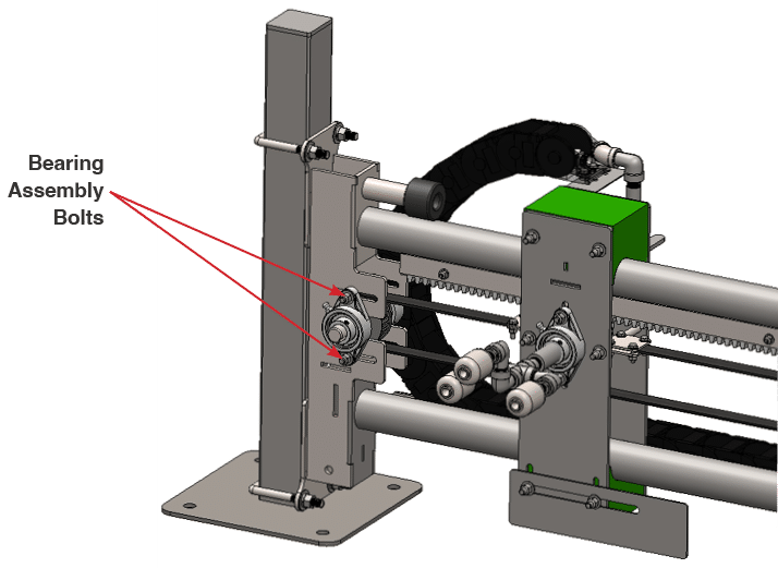
Fig. 7.2.6 – 1 – Belt bearing assembly bolt location
- Locate the drive pulley and using a hex driver, loosen the shaft clamps on each side of the gear box and both bearing shaft collars holding the shaft (Fig. 7.2.5 – 2).
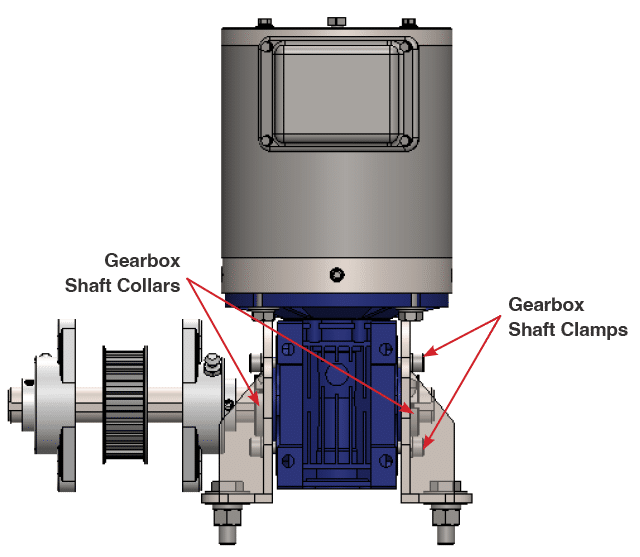
Fig. 7.2.6 – 2 – Gearbox shaft clamps
- Remove the car side bearing block.
- Remove the set screws located in the sprocket hub to separate the keyed taper lock in the drive sprocket.
- Slide the drive shaft out of the drive pulley towards the wall through the gearbox.
- Do not fully remove the drive shaft. Only push it back as far as the wall side bearing block so that the drive sprocket can be fully removed.
- Clean the drive shaft and surrounding area using a cleaning cloth. Remove any debris, old lubricant, or corrosion to ensure a smooth installation of the new sprocket.
- Align the drive sprocket with the belt and slide the drive shaft through the new drive sprocket, ensuring it is properly seated and aligned.
- Ensure that the keyed taper lock is installed in the central hub of the drive sprocket, but do not tighten the set screws.
- While maintaining the drive sprockets alignment with the belt, tighten the set screws for the taper lock on the new drive sprocket using an appropriate Allen wrench. Ensure the sprocket is firmly in place and properly aligned.
- Install the car side bearing block removed in Step 5.
- Tighten the bearing set screws and shaft collar bolts to secure the drive shaft.
- Turn the Main Disconnect switch on the front of the electrical enclosure to the ON position (re-establish power to the wheelblastIT).
7.2.7 Replacing Gearbox #
- Turn Main Disconnect switch on the front of the electrical enclosure to the OFF position.
- If wheelblastIT controls are integrated into sites tunnel controller, ensure all power (motor and control) to the wheelblastIT unit is turned OFF and all outputs to the control solenoids are turned OFF.
- Loosen the bolts holding bearings at the end of the belt (Fig. 7.2.7 – 1). This will be the end opposite the motor (traditionally exit end of wash).
- Slide the bearings forward to relieve tension.

- Disconnect the motor wires to avoid damaging the cable.
- Remove the motor from the gearbox.
- Unthread the 4 bolts along the flange of the gearbox (Fig. 7.2.7 – 2).
- Lift vertically and set aside the motor. Do not to hit or damage the output shaft of the motor.
- Remove the 4 bolts holding the gearbox mounts to the main system frame (Fig. 7.2.7 – 2).
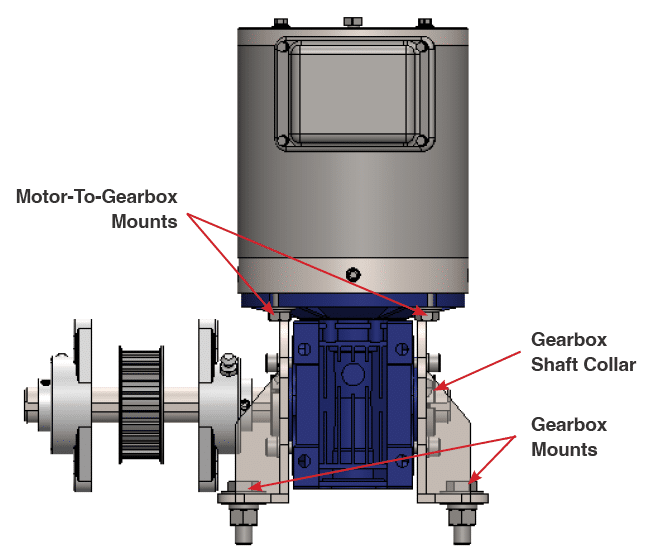
Fig. 7.2.7 – 2 – Gearbox bolt locations
- Loosen the shaft collar towards the wall and remove from the shaft.
- Slide the gearbox off of the shaft.
- There should be a piece of keystock that can be put aside for use upon installation of a new gearbox.
- If using the same gear box:
- Remove the gearbox mounts from the old gearbox and install onto the new gearbox in the same orientation.
- If upgrading to a stainless steel gearbox:
- Using the supplied hardware, install the new gearbox mounts onto the new gearbox in the same orientation as the old unit.
- Slide the new gearbox back onto the shaft with the keystock installed.
- Turning the input side of the gearbox will allow realignment of the keyway to the through hole on the gearbox.
- Align to the mounting holes and reinstall the bolts.
- Reinstall the shaft collar on back side of the shaft.
- Reinstall the motor to the gearbox. Add additional antisieze if needed.
- If using a stainless gearbox, ensure the new shaft adapter is used on the motor shaft going into the gearbox
- Re-connect the motor wires.
- Slide the bearings on and tighten the bolts holding the bearings.
- Use a ruler or tape measure to check the belt deflection and follow the instructions in Appendix 3 – Parts & Service Notes to set the proper belt deflection (1.25”).
- Turn the Main Disconnect switch on the front of the electrical enclosure to the ON position (re-establish power to the wheelblastIT).
