3. Installation #
Installation of the wheelblastIT must conform to local plumbing, electrical, and sanitation codes. The customer is responsible for obtaining all permits and ensuring the following conform to all state and local codes before installing the wheelblastIT.
3.1 Installation Preparation #
Locate where the equipment will be installed with your installer. The wheelblastIT should be installed in the tunnel where the vehicle’s forward motion is stable and consistent.
3.2 Mechanical Installation #
The goal is to position the main frame rail of the wheelblastIT assembly to be 24” from the outside wheel face. The distances listed below and shown in Fig. 3.1 – 1 and Fig. 3.1 – 2 reflect the recommended placement in typical installations.
- Standard Conveyor
- Driver Side
- 38” off the conveyor’s inner rail
- Passenger Side
- 92” off the conveyor’s inner rail
- Driver Side
- Belt Conveyor
- Driver Side/Passenger Side
- 24” from the outer edge of the belt
- Driver Side/Passenger Side
- If using the wheelblastIT controller, determine where the electrical enclosure will be placed in your backroom. Take into consideration the following points:
- Access to HMI screen
- Location of 3ph electric supply for the system
- Location of control wiring from tunnel controller for the system
- Location of any equipment that may be spraying water
- Once the wheelblastIT is positioned in you tunnel, place a level on each vertical post to ensure the unit is level. Next, place a level across the top rail and ensure the unit is level.
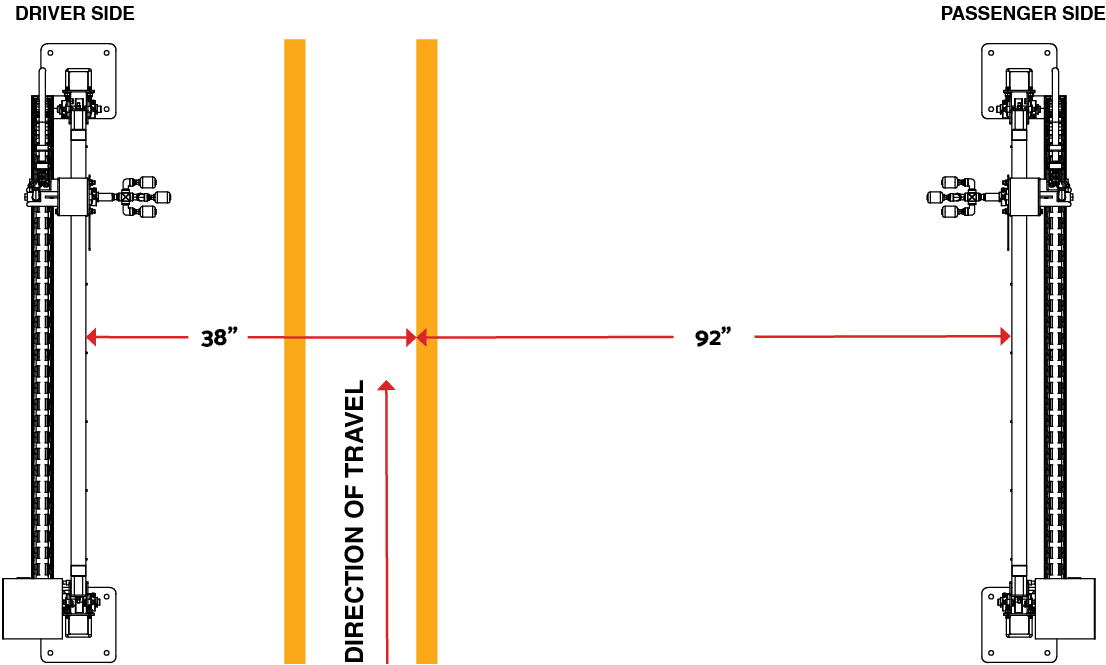
Fig 3.1 – 1 – Standard chain conveyor placement of wheelblastIT assemblies
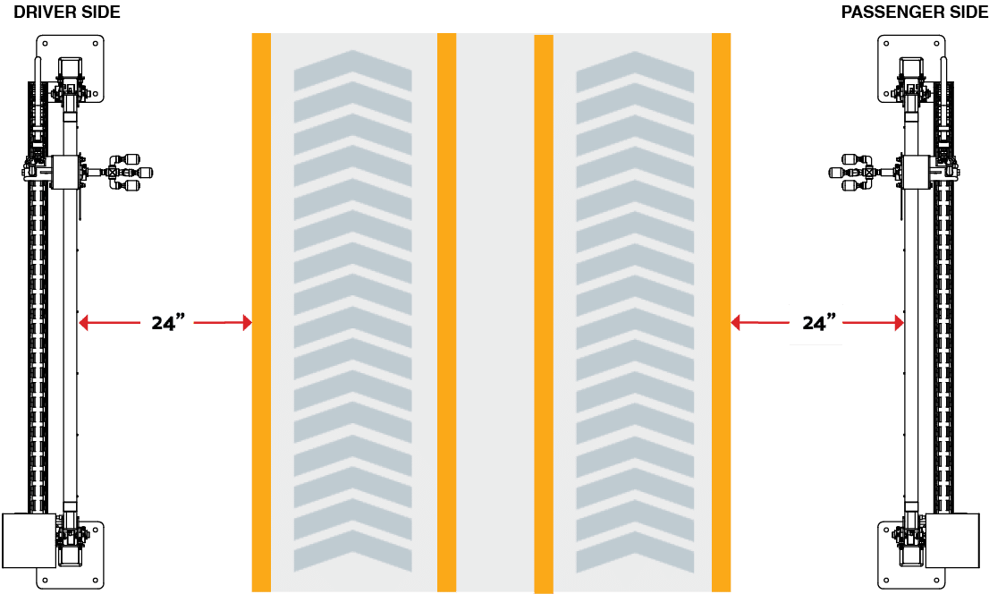
Fig 3.1 – 2 – Belt conveyor placement of wheelblastIT assemblies
3.2.1 Installing Water Lines #
- Connect the HP water hose from the wheelblastIT energy chain to your high-pressure pumping station (pumping station not included).
- Pumping station requires 10-12 gpm @ 800psi
- Recommended: (1) ¾” stainless steel line from pumping station to the location of the wheelblastIT, then split to (2) ½” lines extending to each assembly
3.3 Electrical Installation #
WARNING! Electrical installation to be performed by a qualified electrician. Follow all local codes.
NOTE – When installing cable connections, use dielectric grease of NLGI viscosity grade 2 to minimize the potential for water intrusion shorting the sensor signal or corroding the pins. Reapply whenever cable is disconnected from sensor.
The electrical schematics and connection points in the controller are designated in Appendix 2.
- Run provided sensor cables from innovateIT electrical enclosure to each wheelblastIT assembly. Do not run the sensor cable parallel to any high voltage lines.
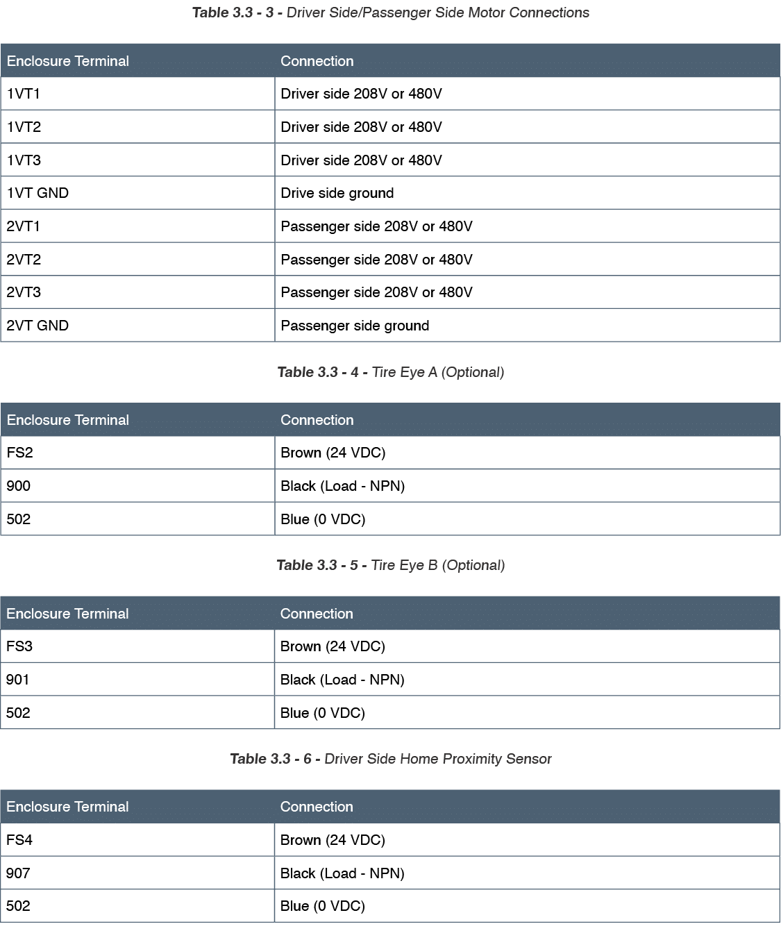
- Make electrical connections as listed in the tables below.
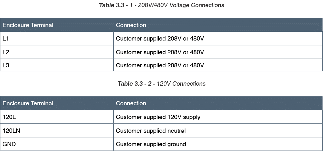
- Run customer supplied power (3PH) to DISC1 according to the system schematic (Fig. 3.3 – 1).
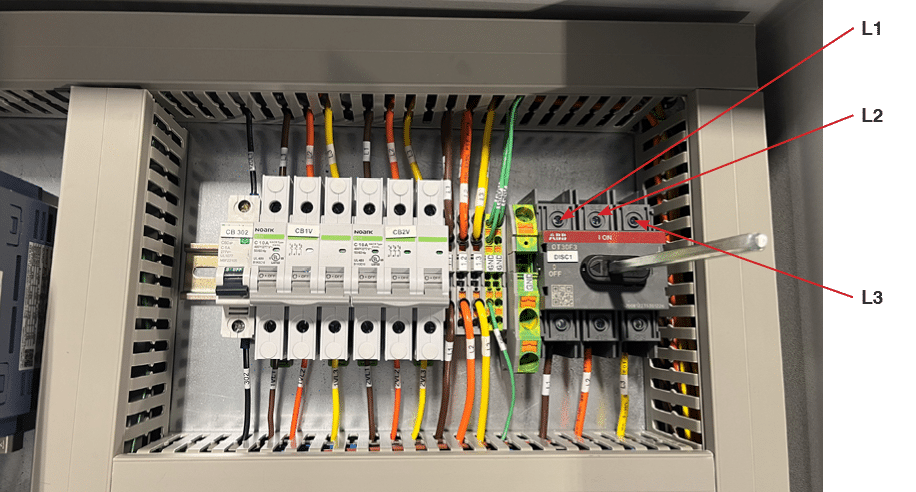
Fig. 3.3 – 1 – Customer 3PH connection
- Connect 120VAC to the 120L1, 120LN, and ground terminal located in wheelblastIT electrical enclosure. (Fig. 3.3 – 2).
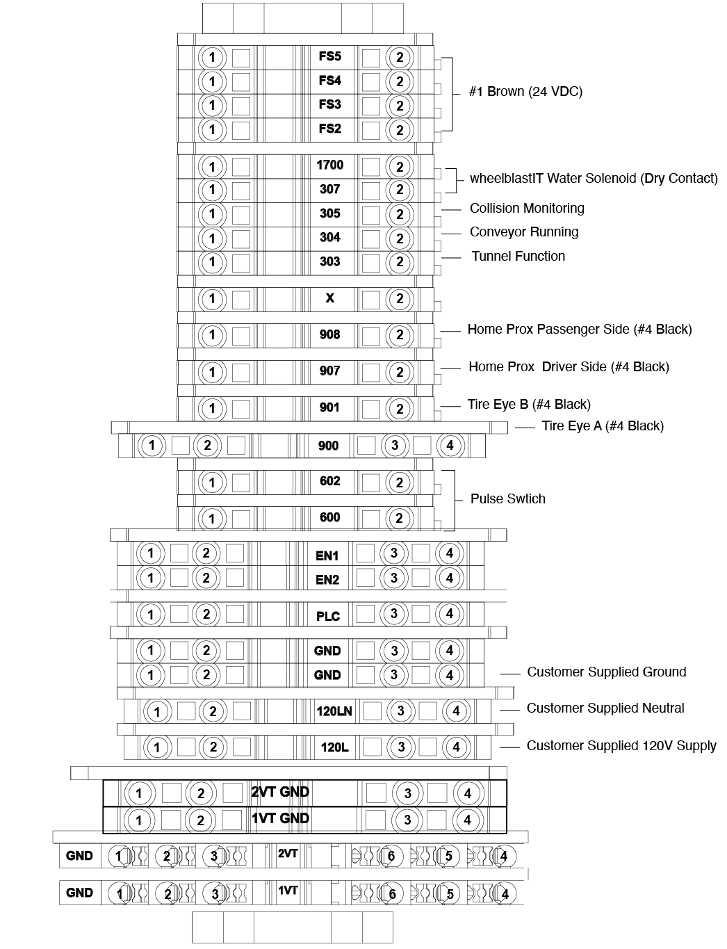
Fig 3.3 – 2 – Electrical enclosure terminal strip connections
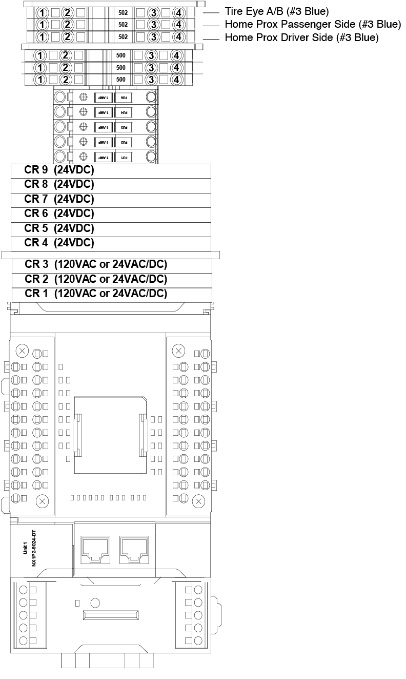
Fig 3.3 – 3 – Electrical enclosure terminal strip connections
3.3.1 Water Solenoid Setup #
Below are detailed instructions for the water solenoid setup within the wheelblastIT system. The configurations listed ensure that the wheelblastIT controller correctly manages water flow and pump operations in accordance with the trolley’s position and forward travel The setup variations are based on the specific type of pump and control method utilized.
- Single Pump Controlled by a Motor Starter (No Solenoid Involved)
This configuration is applicable when a single pump, controlled by a motor starter, is dedicated exclusively to the wheelblastIT without involving a solenoid.
- Power Supply Configuration:
- The tunnel controller supplies power to the motor starter based on the required voltage.
- For 120V applications, constant power (hot) from the tunnel controller should be connected to terminal 307.
- For 24V applications, constant power (hot) should be connected to terminal 107.
- Control Signal Setup:
- Terminal 1700 serves as the “controlled hot” that connects to the motor starter’s A1 terminal.
- A2 terminal of the motor starter should be connected to the neutral line that the tunnel controller uses for other motor starters.
- Pump Controlled by a Variable Frequency Drive (VFD) Dedicated to wheelblastIT
In this configuration, a VFD is used to control the pump exclusively for the wheelblastIT operation.
- Power Supply Configuration:
- For 120V applications, the common of the “VFD FWD” command should be connected to terminal 307.
- For 24V applications, connect the common to terminal 107.
- Control Signal Setup:
- The “VFD FWD” terminal of the VFD should be connected to terminal 1700.
- Shared Pump Controlled by Tunnel Controller with a Separate Solenoid for wheelblastIT
This setup applies when a single pump is utilized for multiple high-pressure applications within the tunnel, but a separate solenoid is employed specifically for the wheel blaster.
- Pump Operation:
- The tunnel controller is responsible for starting the pump.
- Ensure that the tunnel controller is programmed to keep the pump running for the entire duration the car is at the wheel blaster.
- Power Supply Configuration for the Solenoid:
- For 120V applications, constant power (hot) from the tunnel controller should be connected to terminal 307.
- For 24V applications, connect the power to terminal 107.
- Control Signal Setup for the Solenoid:
- Terminal 1700 serves as the “controlled hot” that connects to the solenoid’s A1 terminal.
- The A2 terminal of the solenoid should be connected to the neutral line that the tunnel controller uses for other solenoids.
3.3.2 Remote Connection #
The Tosibox in the electrical enclosure will provide the innovateIT technical support staff remote access to your wheelblastIT control system.
- Connect ethernet cable from your router or network switch to the Tosibox WAN port (Fig. 3.3.2 – 1).
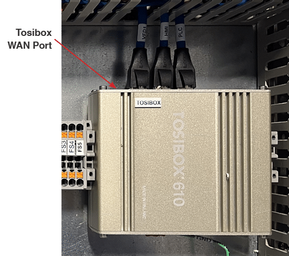
Fig 3.3.2 – 1 – Tosibox WAN port connection for remote support
3.3.3 Setting wheelblastIT Tunnel Controller Function
#
- Begin by assigning the wheelblastIT its own function in the tunnel controller (if needed, contact your tunnel controller provider for assistance).
- Enter the distance from your tire switch to the wheel blaster spray nozzles.
- Subtract 12” and set that value in the tunnel controller.
- Enter the length for which the function will be on (approximately 12”).
- Assign output relay in tunnel controller that will be used (if needed, contact your tunnel controller provider for assistance).