4. Startup & Operation #
WARNING! Check and verify the tightness of all power distribution lines (screw terminals) before the startup process.
NOTE – Ensure all steps and precautions in Section 3 have been completed before starting up the Reclaim System.
4.1 Turning On Power Supply #
- Turn on the utility power from the wash to the Reclaim System.
- Open electrical enclosure and turn on all breakers. Ensure all 4 thermal fuses are pressed in.
- Close electrical enclosure.
- Turn 480VAC Main Disconnect switch on the front of the electrical enclosure to the ON position.
- Wait for the HMI Overview Screen to appear. Verify the date and time displayed on the HMI are correct. If not, refer to Section 6.1 to reset the clock.
4.2 Verifying Air Valve Operation #
- Navigate to the Maintenance screen.
- Press the SYSTEM MANUAL button (Fig. 4.2 – 1). From the drop-down menu, press the MANUAL OVERRIDE button.
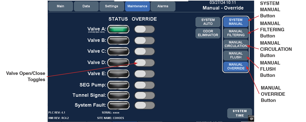
Fig 4.2 – 1 – HMI Maintenance screen and button locations
- Manually turn Valves A, B, C, D, and E on and off by pressing the corresponding toggles to confirm the operation of each (Fig. 4.2 – 1). Valve locations are shown in Fig. 4.2 – 2.
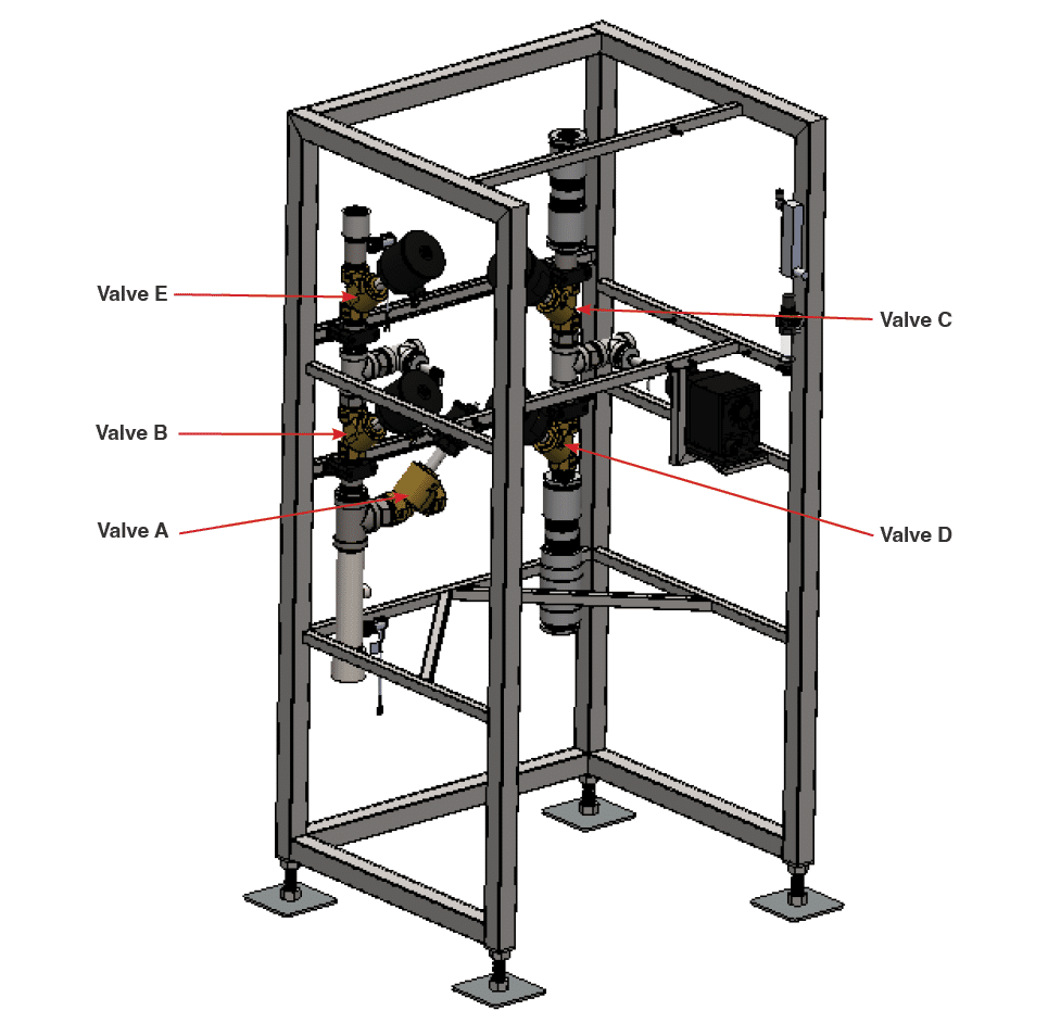
Fig 4.2 – 2 – Valve locations
- Verify that all valves are in their normal state (all closed except Valve A).
- Open is shown by a red indicator present in the site glass.
- Press the SEG PUMP button and ensure the pump turns on (Fig. 4.2 – 1) and that water is flowing to the designated recirculation location (e.g. tunnel pit).
- Toggle tunnel signal from the controller and verify you have a tunnel signal via the status indicator on the HMI (Fig. 4.2 – 1).
4.3 Turning on Water Supply and Filling Tanks #
NOTE – Tanks must be filled under a low-pressure condition.
- From the Maintenance screen, press the SYSTEM MANUAL button. From the drop-down menu, press the MANUAL OVERRIDE button.
- Partially open your municipal water supply line ball valve to allow water to flow into the system.
- From the Maintenance screen, open Valves D and E by pressing the toggles (Fig. 4.2 – 1).
- Fill the tanks until you confirm the system has discharged into the sewer.
- Close Valve D, followed by Valve E.
- Wait 4 hours. This process holds pressure in the system. The captured pressure in the tanks will allow them to saturate more rapidly.
- Fully open municipal water supply line ball valve.
- Initiate a manual flush.
- Navigate to the Overview screen and select SYSTEM MANUAL (Fig. 4.3 – 1).
- Select MANUAL FLUSH
- Allow the system to backflush for 45 minutes-1 hour, or until you have clear, clean, particulate free discharge.
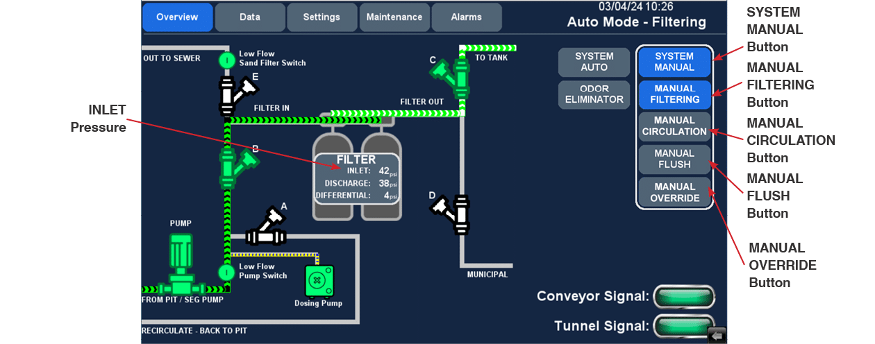
Fig 4.3 – 1 – HMI Overview screen
4.4 Verifying SEG Pump Operation #
- Navigate to the Overview screen and press the SYSTEM MANUAL button (Fig 4.3 – 1).
- Press the MANUAL CIRCULATION button (Fig. 4.3 – 1). Manual circulation allows air to be purged from the line and ensure discharge.
- Press the MANUAL FILTERING button (Fig. 4.3 -1).
- Check the INLET pressure during this process (Fig 4.3 – 1). If the INLET pressure is low (10-15 psi), switch the phasing on the SEG Pump motor, then re-initiate manual filtering and check the INLET pressure again.
- To phase the SEG Pump motor, switch two leads from the motor starter that supplies electrical power to the SEG Pump.
- INLET pressure should be approximately 40-50 psi.
4.5 Starting And Deaerating The Dosing Pump #
- Open the deaeration valve by approximately half a turn (Fig. 4.1.5 -1).
- Press the [100 %] key (Fig. 4.1.5 – 1) and hold it downuntil liquid flows out of the deaeration hose continuously and without any bubbles.
- Close the deaeration valve. The pump is now deaerated.
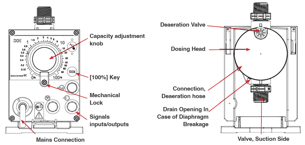
Fig. 4.5 – 1 – DDE Dosing pump components
The Reclaim System comes preloaded with default settings values. There are a number of optional flush settings that can be set from the FLUSH SETUP WIZARD. The adjustable settings will vary based on whether your Reclaim System is filling a tank or direct feeding a high-pressure pump, and your preferred flush settings. The process for making your selections is outlined below.
NOTE – When choosing time of day to flush, total available site water flow needs to be considered.
- Navigate to Settings screen and press the FLUSH SETUP WIZARD button (Fig. 4.6 – 1).
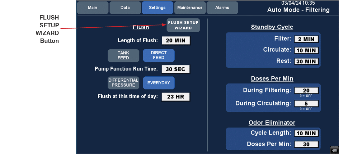
Fig. 4.6 – 1 – HMI Settings screen and FLUSH SETUP WIZARD button
- Set your preferred duration of flush. Duration of the Flush cycle may need to be adjusted depending on season, water quality, and the amount of debris in the tank.
- Select whether your system is TANK FEED or DIRECT FEED.
- TANK FEED > Select when you want the system to run a flush cycle.
- DIFFERENTIAL PRESSURE > Set the differential pressure of the filters at which you want the system to run a flush cycle.
- Select whether you want the flush cycle to run IMMEDIATELY or at a SPECIFIC TIME.
- IMMEDIATELY > The flush cycle will run as soon as the differential pressure of the filters is met.
- SPECIFIC TIME > The flush cycle will run at the specified time of day after the differential pressure has been met.
- EVERYDAY > Set the time of day when you want the system to run a flush cycle based on a 24-hour clock.
- DIRECT FEED > Enter how long your high-pressure pump runs per car.
- Next, select when you want the system to run a flush cycle.
- DIFFERENTIAL PRESSURE > Set the differential pressure of the filters at which you want the system to initiate a flush cycle.
- Select whether you want the flush cycle to occur IMMEDIATELY or at a SPECIFIC TIME.
- IMMEDIATELY > The flush cycle will run as soon as the differential pressure of the filters is met.
- SPECIFIC TIME > The flush cycle will run at the specified time of day after the differential pressure has been met.
- Set the time of day when you want the system to run a flush cycle based on a 24 hour clock
- Set the maximum number of days to allow between flush cycles.
- EVERYDAY > Set the time of day at which you want the system to run a flush cycle based on a 24-hour clock.
- TANK FEED > Select when you want the system to run a flush cycle.
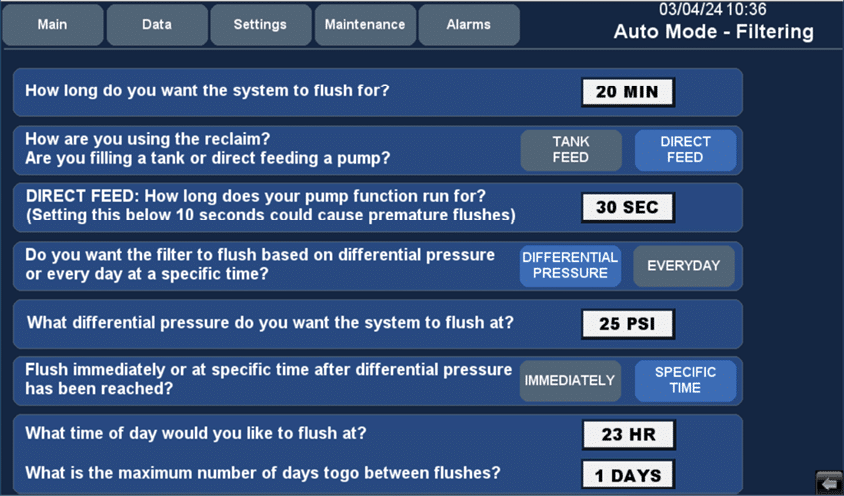
Fig. 4.6 – 2 – FLUSH SETUP WIZARD screen
4.7 System Settings #
- Navigate to the Settings screen and adjust the following settings as needed.
- Standby Cycle – Occurs when there is no tunnel signal. The cycle is a loop of functions that will run when no tunnel signal is present (Fig 4.7 – 1).
Fig. 4.7 – 1 – Standby Cycle function loop in Tank Feed (left) and Direct Feed (right) operating modes
-
- Doses Per Minute – Chemical doses per minute when the system is filtering or recirculating. Chemical will be injected in listed doses per minute when in designated operating state. The amount of chemical required is dependent on multiple factors, including water quality, water circulation, geographic location, and time of year.
- Odor Eliminator – Temporarily injects a controlled overdose of chemical in order to shock the system and neutralize issues commonly associated with reclaim water, such as odor.
- Cycle Length – The length of time the chemical will be injected once the Odor Eliminator is selected.
- Doses Per Minute – Number of additional chemical doses per minute of the Odor Eliminator cycle.
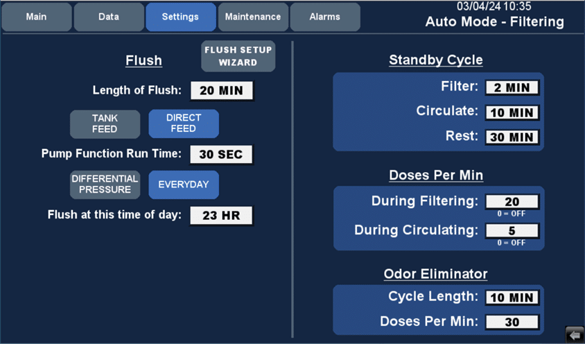
Fig. 4.7 – 2 – HMI Settings screen
4.8 Starting The System #
- Once you have entered your preferred settings, navigate to the Overview screen (Fig. 4.8 – 1).
- Press the SYSTEM AUTO button to start the system.
- Verify controller signals and operation.
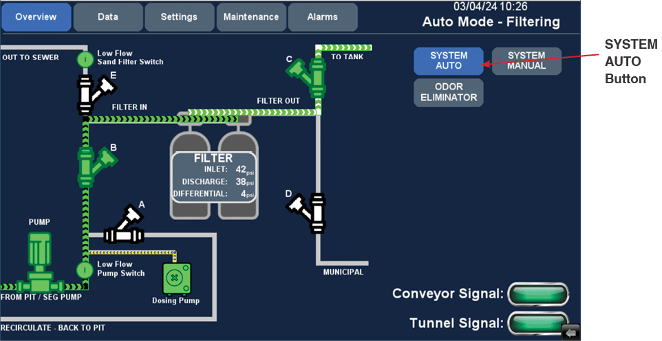
Fig. 4.8 – 1 – HMI Overview screen

