3. Installation #
Installation of the RO System must conform to local plumbing, electrical, and sanitation codes. The customer is responsible for obtaining all permits and ensuring the following conform to all state and local codes before installing the RO System.
3.1 Installation Preparation #
- Locate where the equipment will be installed with your installer. The RO System should be located 4-6 inches from the back wall.
- Use 200 psi hose (Eaton BOSFLEX or equivalent) and heavy-duty stainless steel hose clamps on every connection to ensure reliable operation.
- Lines should be positioned to minimize bends and lines from tanks should hang in a manner to minimize loading on the stainless fittings. The municipal water line and the line out to the wash should be roughly 3 feet from the floor. The Reject line should be roughly 6 feet from the floor.
- If needed, install additional clamps or hose supports to RO frame to reduce movement of hoses during operation.
- All water drains and overflow lines must drain to the floor drain. The RO System plumbing is constructed to allow a visual indication of water flowing to the drain to help diagnose proper system operation. The RO tank has a 2 inch female overflow plug.

Fig. 3.1 – 1 – RO System dimensions and connection locations (Standard Flow/High Flow)
3.2 Mechanical Installation #
WARNING! Do not attempt to remove the carbon filter cover if the pressure in the housing is not zero. If the cap is removed while the unit is pressurized, the cap could cause serious injury or death.
3.2.1 Installing Carbon Block Skid #
The carbon block skid is shipped separate from the main RO skid. Perform the following steps for locating and interfacing the carbon block skid to the main RO skid.
- Line up the carbon block skid to the left of the main RO skid and use the leveling feet to ensure both the frames are level and at the same height.
- Loosen the groove coupling.
- Slide the carbon block groove nipple to the groove coupling and tighten back up (Fig. 3.2.1 – 1)
- Bolt the carbon block skid to the RO skid using (4) 4-inch bolts.
- Route the two cables with DIN connectors, located at the electrical enclosure and labeled “In” and “Out” to the inlet and outlet pressure transducers on the carbon block skid.
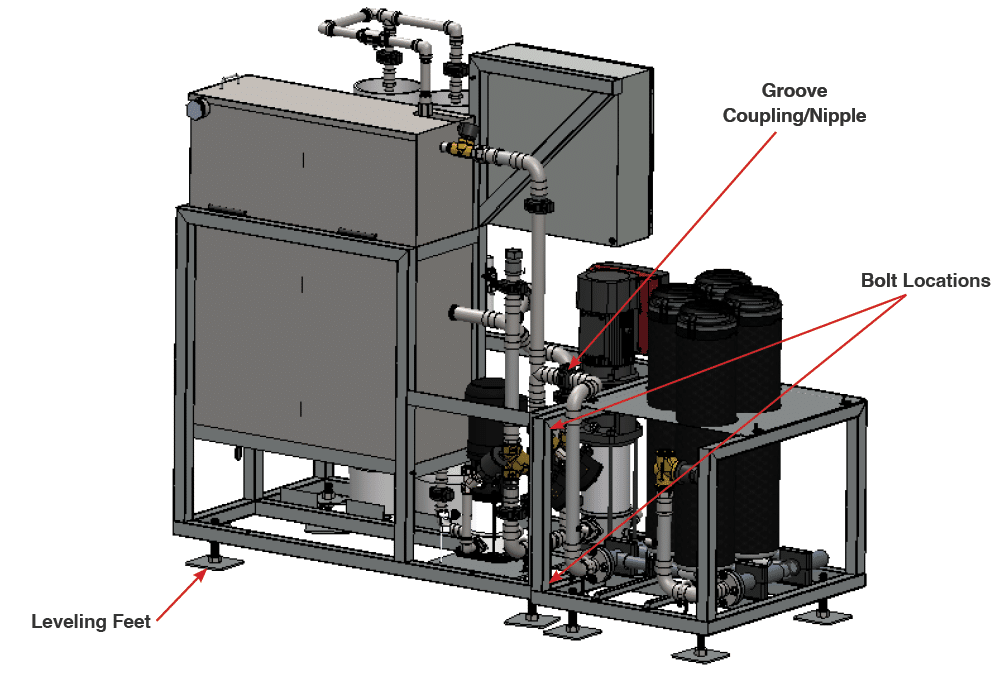
Fig. 3.2.1 – 1 – Carbon Block skid installation
3.2.2 Installing Air Supply #
- Install an air supply to the ¼” push connector air regulator. Verify air supply can supply 3CFM at 80-100 psi, and adjust the air regulator to 80-100 psi (Fig. 3.2.2 – 1).
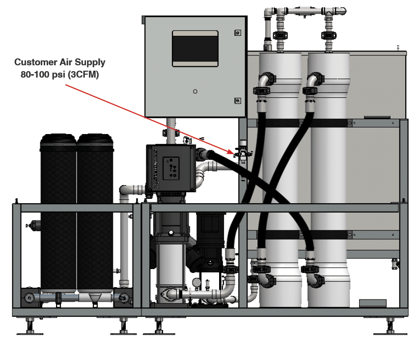
Fig. 3.2.2- 1 – Air regulator supply line connection
3.2.3 Installing Water Lines #
- Connect a 1.5” MNPT hose to the municipal water inlet (Fig. 3.2.3 – 1). Verify municipal water can supply 40GPM @ 40-60 psi (see Table 2.2 – 1).
- Connect a 1.5” MNPT hose to the Reject Outlet (Fig. 3.2.3 – 1). Reject water should be plumbed to either a reject tank, high-pressure pump stand, or drain.
- Connect a 1” MNPT hose to the Spot-Free Outlet (Fig. 3.2.3 – 1). The Spot-Free Outlet can be plumbed directly to a single applicator in the wash or to a solenoid bank that supplies spot-free water to multiple applicators.
- (Optional) Connect a 2” MNPT hose to the Drain Port (Fig. 3.2.3 – 1).
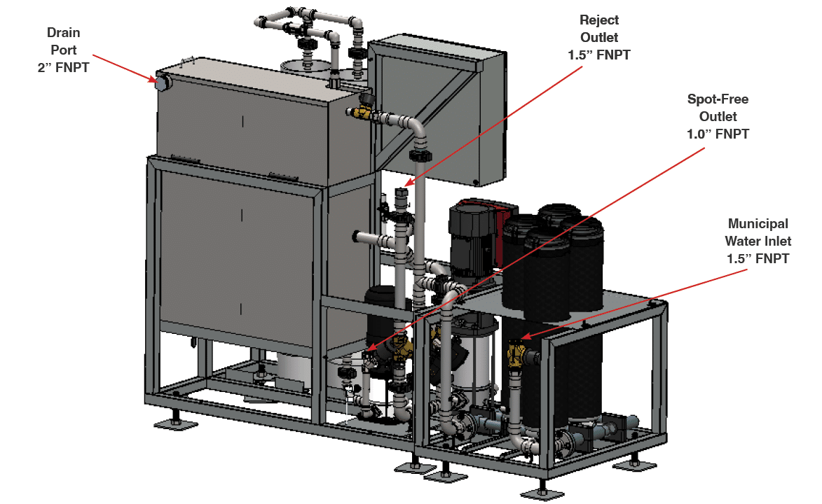
Fig. 3.2.3 – 1 – Water line connections
3.3 Electrical Installation #
WARNING! Electrical installation to be performed by a qualified electrician. Follow all local codes.
The electrical schematics and connection points in the controller are designated in Appendix 2. The Main Control Disconnect (DS1) is used to disconnect all power to the unit. All penetrations should be made through the bottom of the enclosure.
NOTE – Each electrical enclosure has a serial number located inside the controller on the lower left side of the enclosure door. This number should be referenced when requesting support on the RO System, as this number links to both the controller software and hardware.
WARNING! The Main Disconnect power must be turned off at the disconnect switch on the front of the enclosure before opening the RO System controller for maintenance.
- Locate customer network interface (Fig. 3.3 – 1) and connect RJ-45 network cable. This will provide innovateIT Car Wash equipment with VPN remote access to the system.
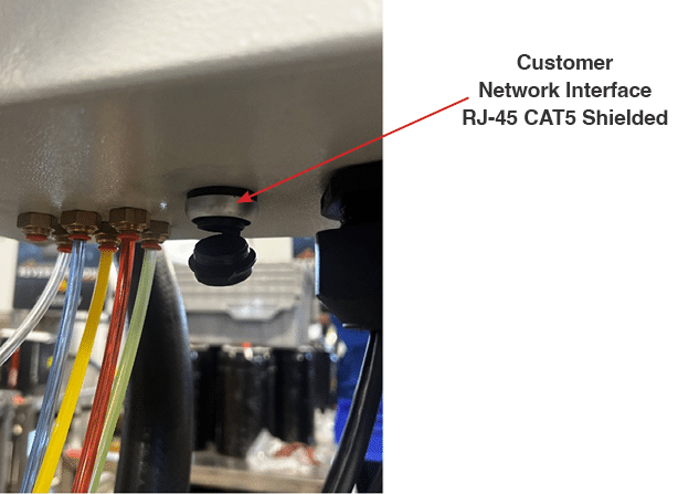
Fig. 3.3 – 1 – Customer network interface location
- Connect wires from the tunnel controller to command the RO unit to supply water to terminals 1003A and 1003C (Fig. 3.3 – 2).
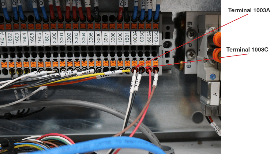
Fig. 3.3 – 2 – Location for terminals 1003A and 1003C
- Locate power supply knockout location (lower left). Drill and install a cable gland for 480VAC 3PH power supply.
- Run customer supplied power (480VAC/3PH) to DS1 according to the system schematic (Fig. 3.3 – 5).
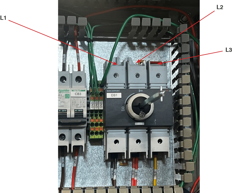
Fig. 3.3 – 5 – Customer 480VAC/3PH connection
- Check the direction of rotation of the Transfer Pump motor by bump starting the MS1 contact (Fig. 3.3 – 6). The correct direction of rotation is indicated by the arrows on the motor fan cover (Fig. 3.3 – 7). The pump should rotate counter-clockwise when viewed from the motor end. This needs to be done by the electrician prior to completing electrical installation.
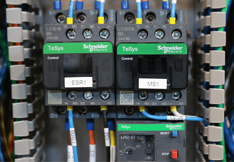
Fig. 3.3 – 6 – MS1 contact location
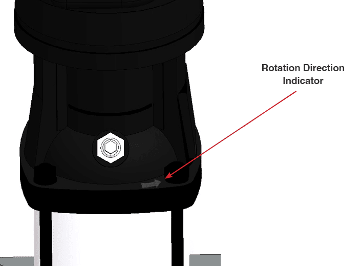
Fig. 3.3 – 7 – Arrow indicating direction of rotation on the Transfer Pump casing
- If the pump fan rotates clockwise, stop the pump, turn off the Main Disconnect and the utility supply power, and interchange any two of the incoming 480VAC/3PH supply wires.
