4. Startup & Operation #
NOTE – Ensure all steps and precautions in Section 3 have been completed before starting up the RO System. Verify phase rotation from utility power supply to the RO System. This is critical for pump rotation to operate correctly. Going to START mode (which starts the RO pump) before purging air from the pump can result in a compromised pump shaft seal or, if left long term, may require the pump to be replaced.
4.1.1 Turning On Air & Power Supply #
- Verify all drain ports are closed (membrane housing, carbon manifold, and RO tank). The ball valves are perpendicular to the unit when closed, and inline when open. See Appendix 1 for drain valve locations.
- Turn on air supply to the RO System and set the air regulator to 80 psi.
- Turn on the utility power from the wash to the RO System.
- Open electrical enclosure and turn on all breakers. Ensure all 4 thermal fuses are pressed in.
- Turn 480VAC Main Disconnect switch on the front of the electrical enclosure to the ON position.
- Wait for the HMI Overview Screen to appear. If not, please contact support@innovateITcarwash.com for more information.
- Confirm positions of Process Valves.
4.1.2 Turning On Water Supply & Purging Carbon Blocks #
NOTE – Confirm the proper supply voltage on all three phases using a multi-meter.
- Partially open your municipal water supply line ball valve to allow water to flow into the system.
- Verify the pressure at the Inlet and Outlet of the carbon filter on the HMI (see Fig. 4.1.3 – 1).
- Press down the red air valve on top of each of the carbon filter housing covers to bleed air out of the system. Release the air valve when water stream is emitted from the red valves. This process may take 10-15 MINUTES or more but it is a critical step to protect the system during initial start-up or after any maintenance during which air could enter any part of the system. (do not pull or remove yellow tag).
4.1.3 Purging The Production & Transfer Pumps #
NOTE – You may hear a loud noise as the membranes pressurize and the top and bottom ports seat themselves.
- On the OVERVIEW screen of the HMI, press the STOP button followed by the MANUAL button to put the system into MANUAL mode.
- Navigate to the AIR VALVE TESTING PAGE (see Fig. 4.1.3 – 1) by pressing the square in the upper right corner of the HMI.
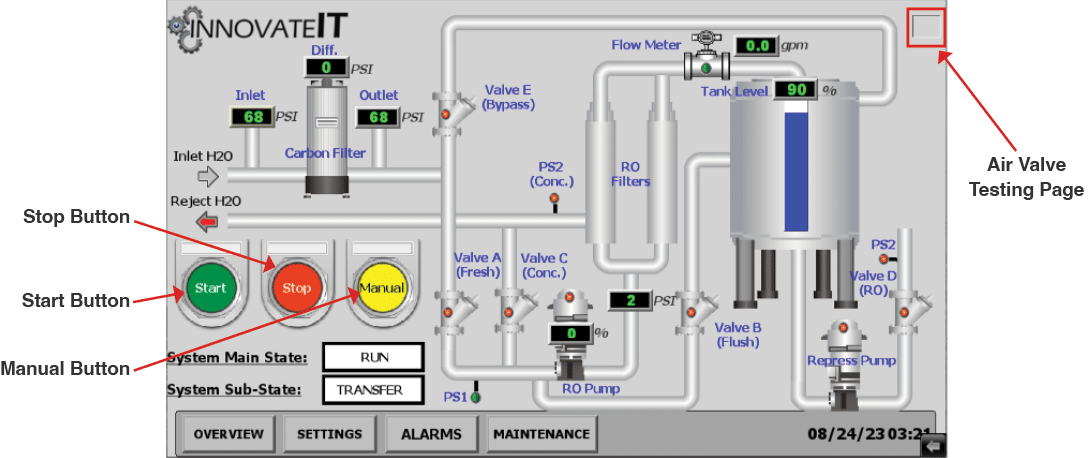
Fig. 4.1.3 – 1 – HMI Overview Screen and Air Valve Testing Page location
- Open Valve A and Valve C to allow water to flow to the Production Pump and through the membranes (Fig. 4.1.3 – 2)
- Valve A needs to remain open while priming the Production Pump. This allows water to start filling the RO storage tank and for municipal water to saturate the membranes.
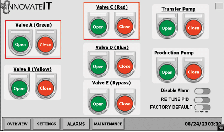
Fig. 4.1.3 – 2 – Air Valve Testing Page
- Once water can be seen flowing into the tank from the membranes, fully open your municipal water supply line ball valve.
- Loosen the Production Pump priming vent plug with a 10mm wrench until there is a constant stream of water, then tighten the vent plug to close (Fig. 4.1.3 – 3).
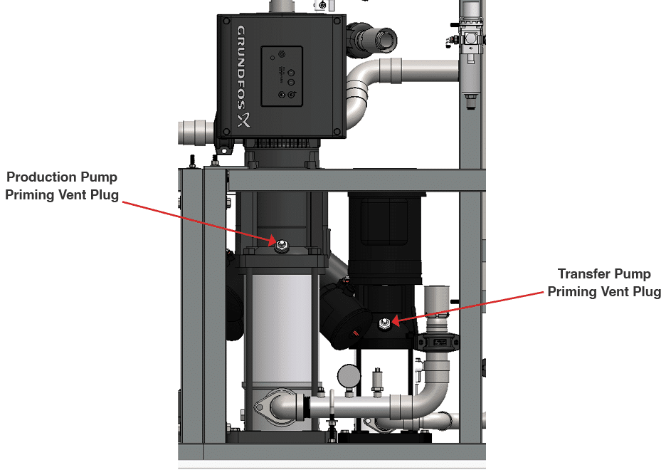
Fig. 4.1.3 – 3 – Production and Transfer Pump priming vent plug location
- Once the tank level is about 25% filled (visually check), close Valves A and C.
- Loosen the Transfer (Re-Pressurization) Pump priming vent plug with a 10mm wrench until there is constant stream of water, then tighten the vent plug to close (Fig. 4.1.3 – 2).
4.1.4 Filling The Tank #
- Return to the OVERVIEW screen and ensure the system is in MANUAL mode.
- Navigate to the MAINTENANCE screen.
- Press the START on the TANK FILL (Fig. 4.1.4 – 1).
- Running the TANK FILL will open the bypass valve and fill the tank with concentrate water (not permeate).
- Once the tank reaches the desired fill level (just below the overflow plug) , press SET on the TANK SPAN.
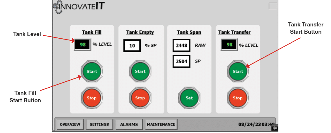
Fig. 4.1.4 – 1 – HMI Maintenance Screen and Tank Fill
4.1.5 Tank Transfer & Secondary Pump Purging #
- Return to the MAINTENANCE screen.
- Ensure your RO applicator solenoids are open and water can flow freely to the wash.
- Once the solenoids are open, press START on the TANK TRANSFER (Fig. 4.1.4 – 1).
- After starting the TANK TRANSFER, prime the Transfer Pump again by following the instructions in step 7 of Section 4.1.3.
- Allow the tank to drain to roughly 60% before pressing STOP on the TANK TRANSFER to remove any residual air.
- Return to the OVERVIEW screen and press the START button (Fig. 4.1.5 – 1). If the system registers an alarm during this process, press the STOP button. Navigate to the ALARMS page and press RESET. Return to the OVERVIEW screen and press the START button again. This may occur a couple of times during startup as all the air is purged from the system.
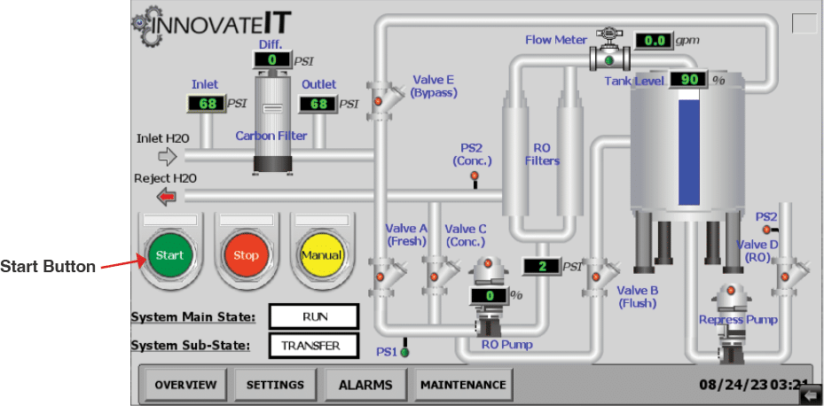
Fig. 4.1.5 – 1 – Starting the system from the HMI Overview screen
- The system will now initialize. You will be able to see the differential pressure across the filters, pump performance, and the current GPM flow rate of the system.
- With the system running, purge the Production Pump by following the instructions in step 5 of Section 4.1.3. This will remove any excess air stuck in the impellers.
- Verify the Production Pump shuts down once the RO tank is full, and the system goes into FLUSH mode after 15min of inactivity.
The initial RO water produced will need to be dumped down the drain. During the first 2 hours of RO production the water is high concentrate. The initial TDS from the unit will be high (50-150 PPM) because of manufacturing chemicals rinsing from the dry membrane.
The TDS will slowly go down as the unit operates, stabilizing in the 1-20 PPM TDS range (based on the TDS of the feed water) within the first few hours of operation. If the TDS of the RO remains higher than 20 PPM a seal in the RO housing may be damaged. In this case, the operator will need to identify the damaged seal ring and replace it.
With new membranes, normal TDS will remain below 10 TDS.
4.2 System Operation #
NORMAL OPERATING CONDITIONS
The system has two normal operating conditions: Run/Production and Flush.
- Run/Production – When the tank drops below 75%, the pump will ramp up speed to meet the targeted flow rate until the tank reaches 95%
- Flush – Occurs after 15 minutes of inactivity. The flush replaces high TDS concentrate water that is surrounding the membranes with low TDS permeate water.
ABNORMAL OPERATING CONDITIONS
The system’s only abnormal operating condition is when it enters into a Bypass.
- Bypass – Occurs when the demand from the car wash exceeds the production capacity of the system and the tank level falls below 25%. The system will open the bypass valve and fill the tank with municipal water until it reaches 35%.
- The TDS of the water in the tank will be high momentarily due to the feed of high concentrate water.