5. Service & Maintenance #
The best method to maintain the wheelblastIT is to take a few minutes daily to examine the unit for leaks or any indication of a mechanical or electrical fault.
If a change in performance or operation is observed, it is essential to take corrective action quickly to minimize the potential damage to the system.
There are elements of the system that will require normal maintenance actions. These items are listed in the following section.
5.1 Service Schedule #
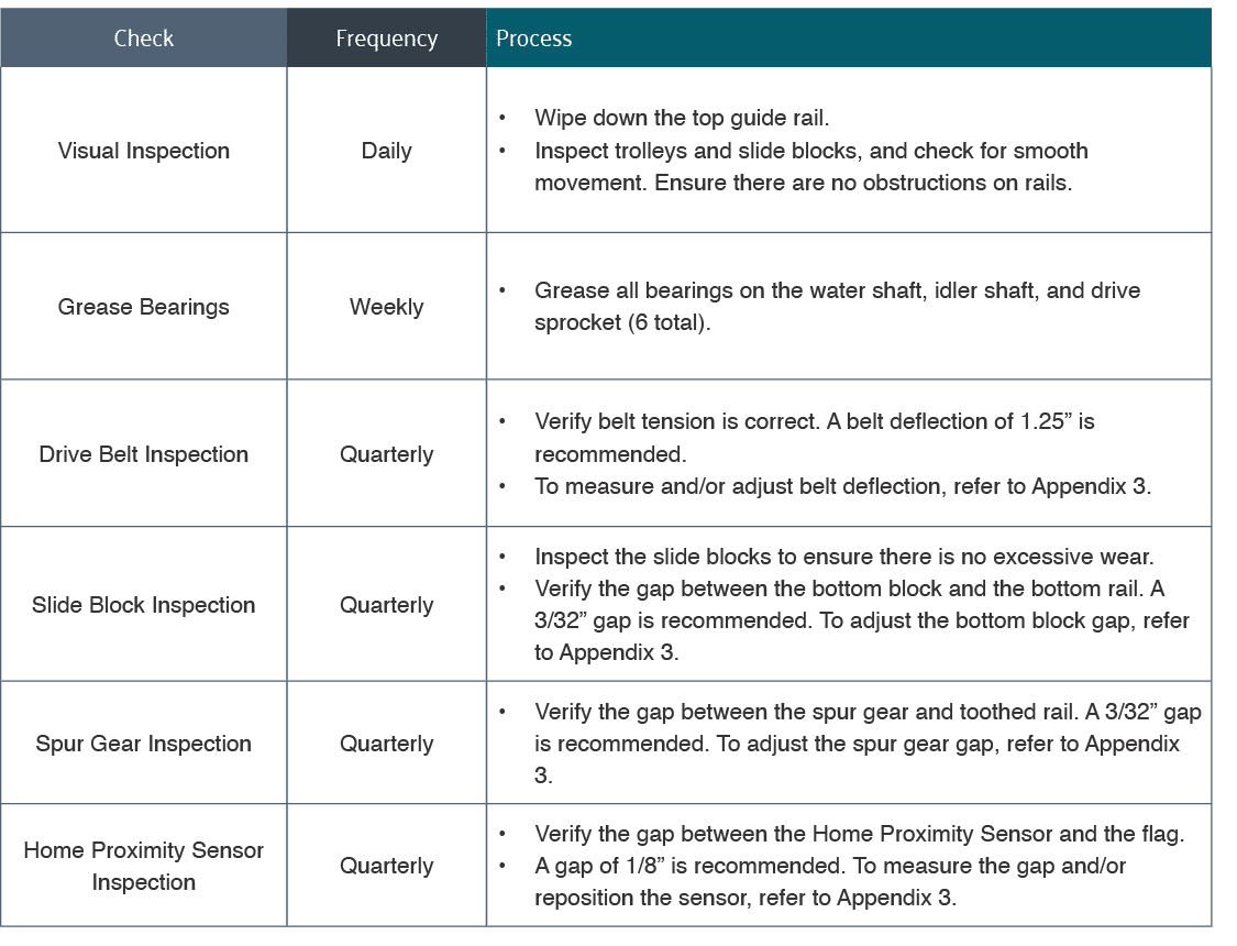
Table 5.1 – 1 – Service schedule