3. Installation #
Installation of the Reclaim System must conform to local plumbing, electrical, and sanitation codes. The customer is responsible for obtaining all permits and ensuring the following conform to all state and local codes before installing the Reclaim System.
3.1 Installation Preparation #
- Review Appendix 1 for the typical backroom configuration and placement of the Reclaim System.
- Locate where the equipment will be installed with your installer. The Reclaim System should be located 4-6 inches from the back wall.
- Use 200 psi hose (Eaton BOSFLEX or equivalent) and heavy-duty stainless steel hose clamps on every connection to ensure reliable operation.
- Use 100 psi pneumatic air lines for air connections and any maintenance related replacements.
- Lines should be positioned to minimize bends, and lines from tanks should hang in a manner to minimize loading on the stainless fittings.
- If needed, install additional clamps or hose supports to the Reclaim System frame to reduce movement of hoses during operation.
- All water drains and overflow lines must drain to the floor drain.
- The filter flush line must drain to the oil separator tank, and the plumbing must be able to flow up to 30 GPM for Standard Flow units and 60 GPM for High Flow units.
- The recirculation line should be directed to flow into the pit before returning to the first waste water tank.
- Ensure the wash supply tank is equipped with overflow to sewer in the event of excess reclaim production.
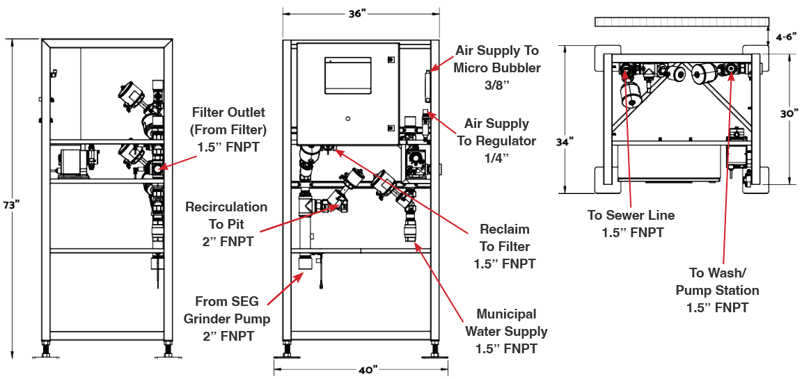
Fig. 3.1 – 1 – Reclaim System frame dimensions and connections
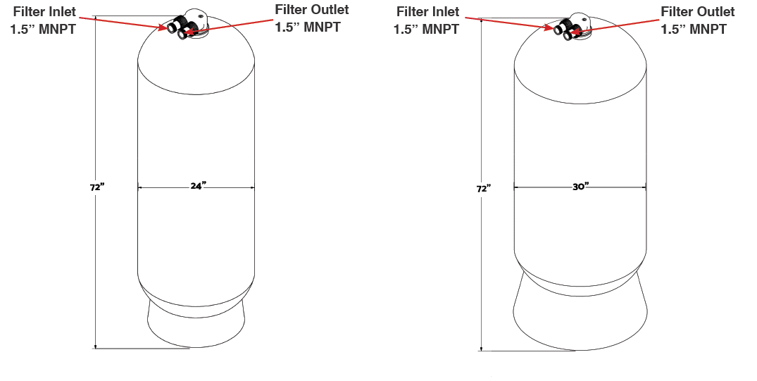
Fig. 3.1 – 2 – Standard Flow (left) and High Flow (right) Reclaim System filter dimensions and connections
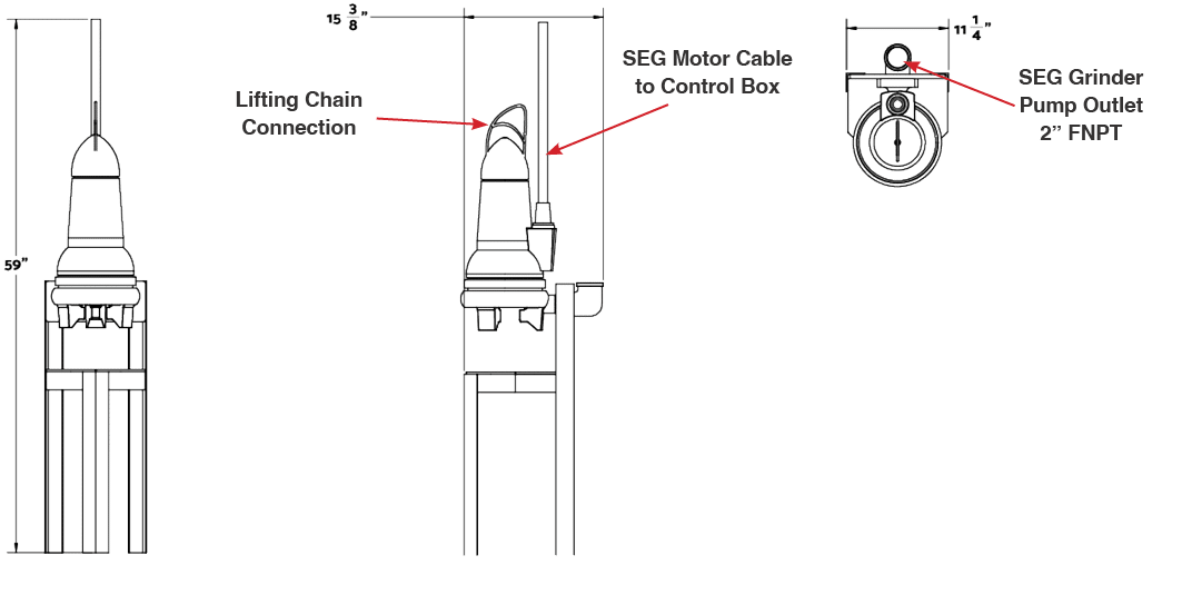

Fig. 3.1 – 4 – Micro bubbler dimensions and connections
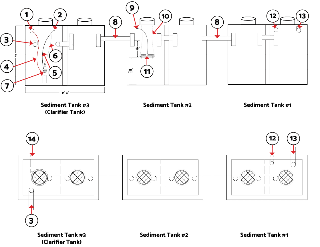
Fig. 3.1 – 5 – Three sediment tank configuration
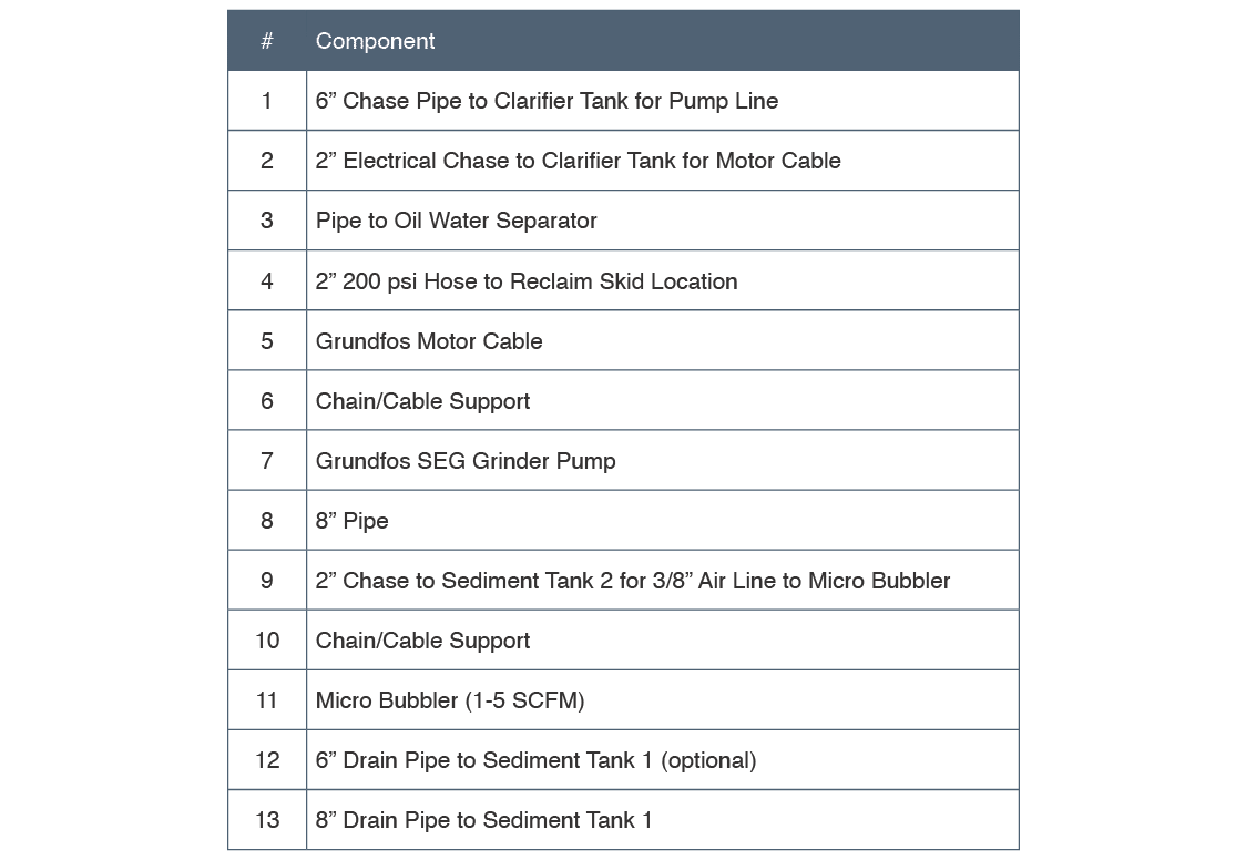
Table 3.1 – 1 – Three sediment tank components
3.2 Mechanical Installation #
3.2.1 SEG Grinder Pump Installation #
The SEG Grinder Pump should be installed in the clarifying tank (Fig. 3.1 – 5).
- Attach 2” hose (#9 in Fig. 3.1 – 5) to the outlet of the SEG base using a 2” NPT hose barb (Fig. 3.2.1 – 1).
- Lower SEG into last division of the settling tanks with the provided lifting chain.
- Connect the top of the chain to a location that is convenient for movement/removal of the pump.
- Connect the 2” hose to the ‘From SEG Grinder Pump’ connection (Fig. 3.1 – 1).
- Run the wire from the SEG pump to the control box as shown in Section 3.3 – Electrical Installation
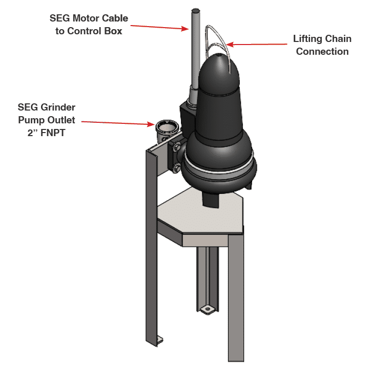
Fig. 3.2.1 – 1 – Grundfos SEG Grinder Pump connection locations
3.2.2 Micro Bubbler Installation
The micro bubbler may also be suspended using the chain or rope if your settling tanks go long periods between cleanings. It is recommended to suspend the bubbler while the tank is empty to verify that it sits level while suspended.
- Attach chain, or rope, to the holes on each end of the bubbler frame (Fig. 3.2.2 – 1).
- Attach 3/8” polytube to the push connect between the two bubbler discs installed in the tank so it can be routed properly (Fig. 3.1 – 4).
- Using the chain or rope attached to the bubbler frame, lower the bubbler into the second-to-last section of the settling tanks. The bubbler frame should be suspended approximately 18” below the surface level of the water line and at least 18” from the bottom of the tank.
- Route the 3/8” polytube to the outlet of the airflow meter on the front of the Reclaim System’s main frame (Fig. 3.1 – 1, ‘Air Supply To Regulator’). The flow meter should be set to roughly 2 cfm.
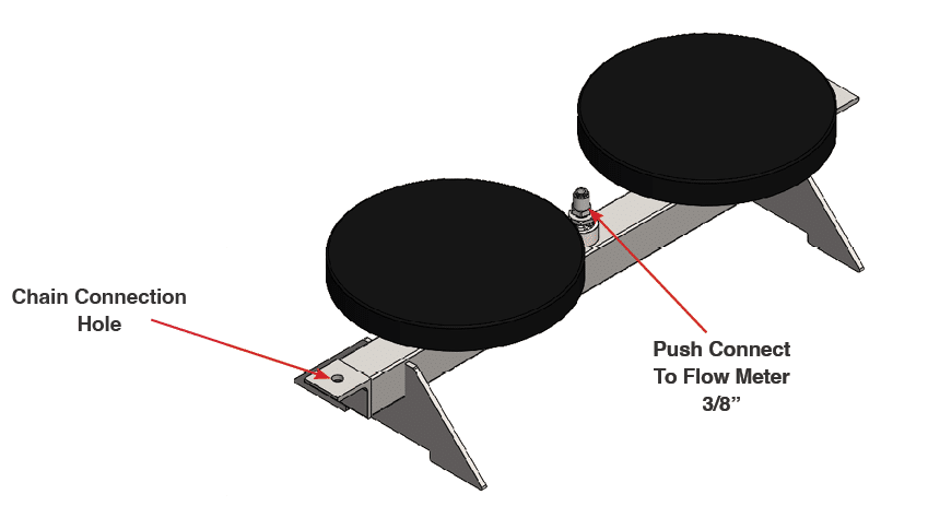
Fig. 3.2.2 – 1 – Micro bubbler connection locations
#
3.2.3 Installing Air Supply #
- Install an air supply to the ¼” push connector air regulator. Verify air supply can supply 3CFM at 80-100 psi, and adjust the air regulator to 80-100 psi (Fig. 3.2.3 – 1).
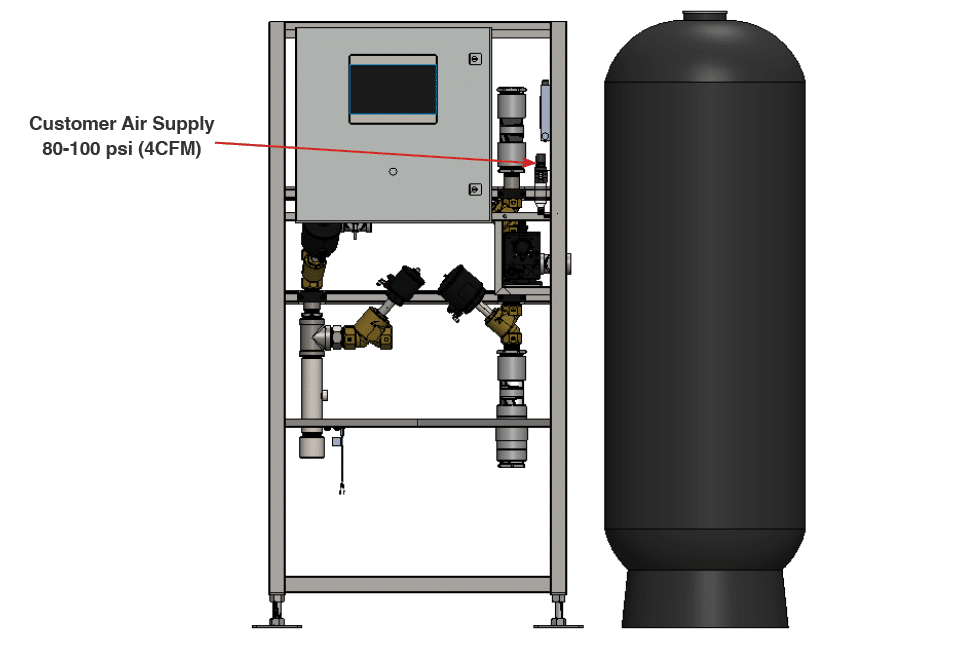
Fig. 3.2.3 – 1 – Air regulator supply line connection
3.2.4 Installing Water And Drain Lines #
The main frame containing the control box and valve manifolds should be located as close to the settling tanks as possible to reduce the amount of plumbing needed.
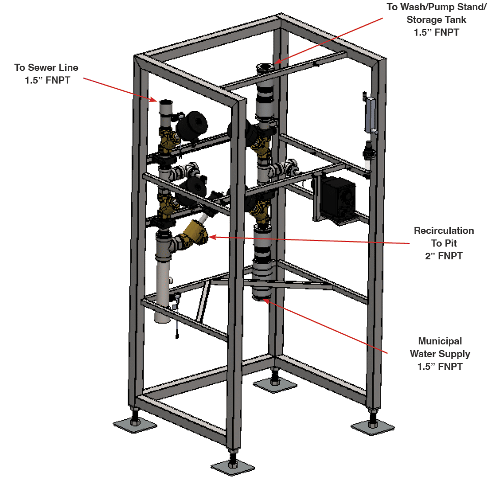
- Connect a 1.5” municipal water feed line to the Municipal Water Supply connection (Fig. 3.2.4 – 1). There is a check valve to ensure that no reclaim water can get into the municipal feed in the event of serious filter failure.
- It is recommended to ensure your municipal supply line ball valve is accessible before installing the Reclaim System.
- Connect a 1.5” line to the To Wash/Pump Stand/Storage Tank connection (Fig. 3.2.4 – 1) to feed your reclaim storage or pump stand.
- Connect a 1.5” line to the To Sewer Line connection (Fig. 3.2.4 – 1).
- It is important that this water is removed from your reclaim water loop because it contains everything the filters have pulled from your reclaim water. Introducing this water back into the loop concentrates the water with the removed particles and rapidly increases the pressure drop across the filters.
- Connect a 2” line to the Recirculation To Pit connection.
Fig. 3.2.4 – 1 – Reclaim System main frame connection locations
3.2.5 Filling Multimedia Filters #
NOTE – Store media in a dry location prior to installation. Wet media poses a significant challenge in the filter filling process.
- Place the filter in the desired location(s). It is recommended that the filter be placed to the right of the main frame when facing the system to simplify plumbing connections.
- Filters should not be filled until the Reclaim System is to be used (within ~48 hours). Water will stagnate if left too long.
- Remove filter head.
- Place duct tape or similar over filter output tube.
- Fill filter approximately 30% (18”) with fresh water.
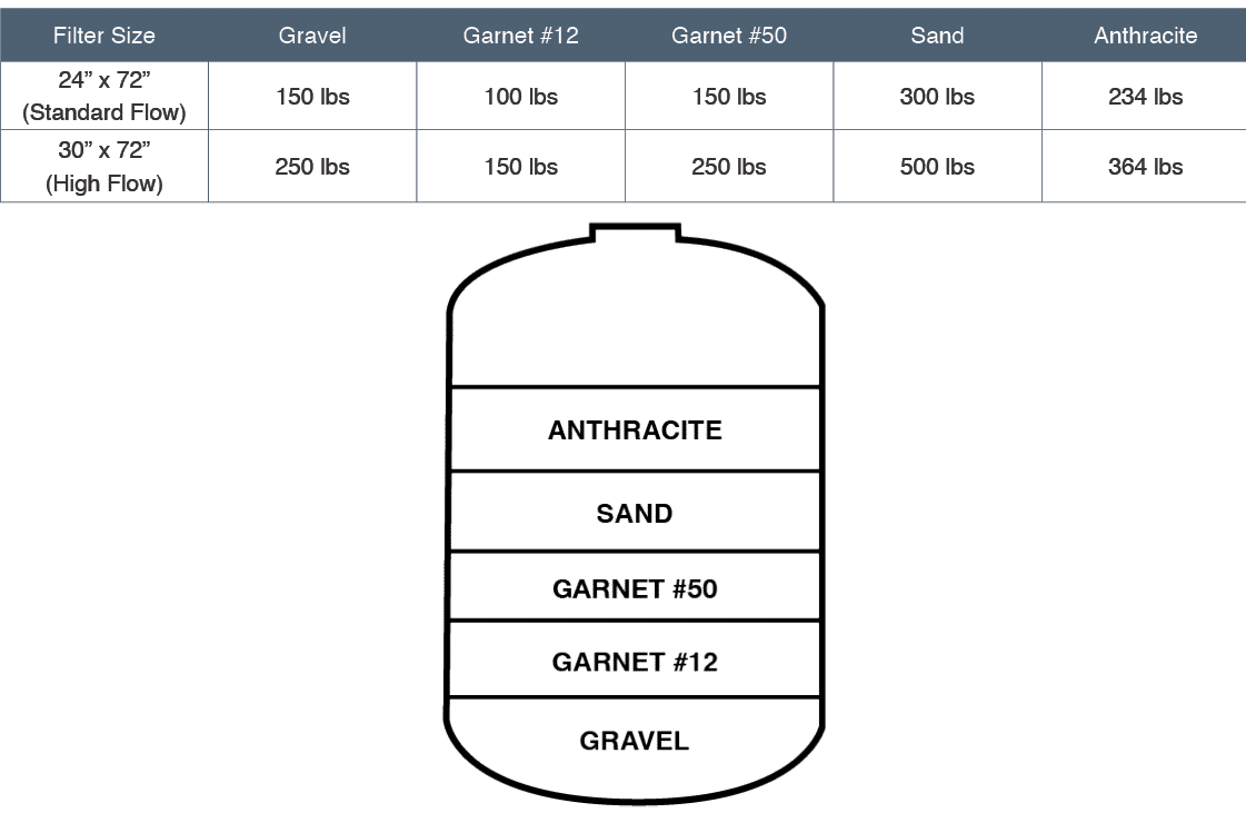
- Using the supplied funnel, CAREFULLY fill the filter with media in the order listed in Table 3.2.5 – 1 below and as depicted in Fig. 3.2.5 – 1.
NOTE – Damage to the distributor will occur if filled too quickly.
Table 3.2.5 – 1 – Multimedia Filter filling order and quantities
Figure 3.2.5 – 1 – Multimedia Filter filling order
- Remove tape from filter output tube.
- Fill remaining filter volume with fresh water.
- ** FOR 30 FILTER ONLY** If the filter is supplied with an adapter flange, attach the adapter flange to the top of the filter housing using the supplied hardware.
- Install Clack D1403 cross flow head (Fig. 3.2.5 – 2).
- Install Clack V4430 quick connect adapters (Fig. 3.2.5 – 2)
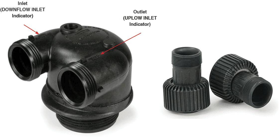
Fig. 3.2.5 – 2 – Clack D1403 cross flow head (left) and Clack V4430 quick connect adapters (right)
3.2.6 Plumbing Multimedia Filters
#
- Plumb the unfiltered water from the To Filter Inlet connection to the DOWNFLOW INLET side of the filter (Fig. 3.2.6 – 1).
- DOWNFLOW INLET is indicated on the top of the Clack head (Fig. 3.2.5 – 2)
- Plumb the From Filter Outlet connection to the UPFLOW INLET side of the filter head (Fig 3.2.6 – 1).
- UPFLOW INLET is indicated on the top of the Clack head (Fig. 3.2.5 – 2)
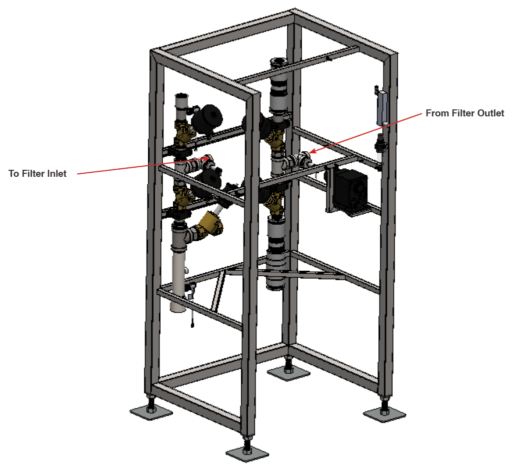
Fig. 3.2.6 – 1 – Main skid multimedia filter plumbing connections
3.3 Electrical Installation #
WARNING! Electrical installation to be performed by a qualified electrician. Follow all local codes.
The electrical schematics and connection points in the controller are designated in Appendix 2. The Main Control Disconnect (DS1) is used to disconnect all power to the unit. All penetrations should be made through the bottom of the enclosure.
NOTE – Each electrical box has a serial number located inside the controller on the lower left side of the enclosure door. This number should be referenced when requesting support on the Reclaim System, as this number links to both the controller software and hardware.
WARNING! The Main Disconnect power must be turned off at the disconnect switch on the front of the enclosure before opening the Reclaim System controller for maintenance.
- Locate customer network interface (Fig. 3.3 – 1) and connect RJ-45 network cable. This will provide innovateIT Car Wash equipment with VPN remote access to the system.
- Locate power supply knockout location (lower left). Drill and install a cable gland for 480VAC 3PH power supply.
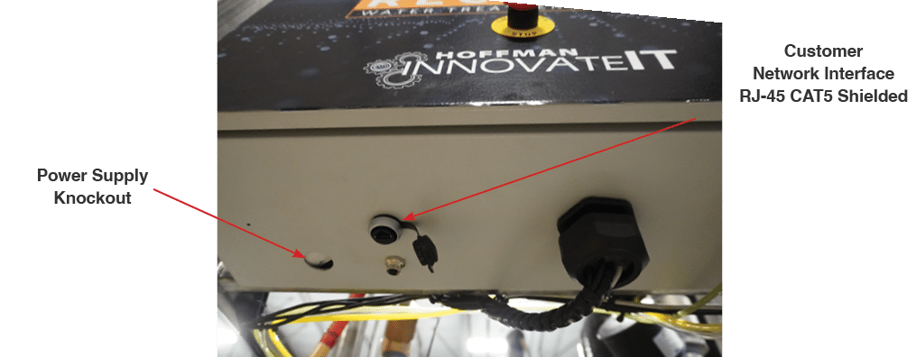
Fig. 3.3 – 1 – Customer network interface and power supply knockout locations
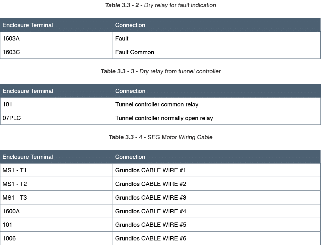
- Make electrical connections as listed in the tables below.
Table 3.3 – 1 – Wire to dry relay on tunnel controller
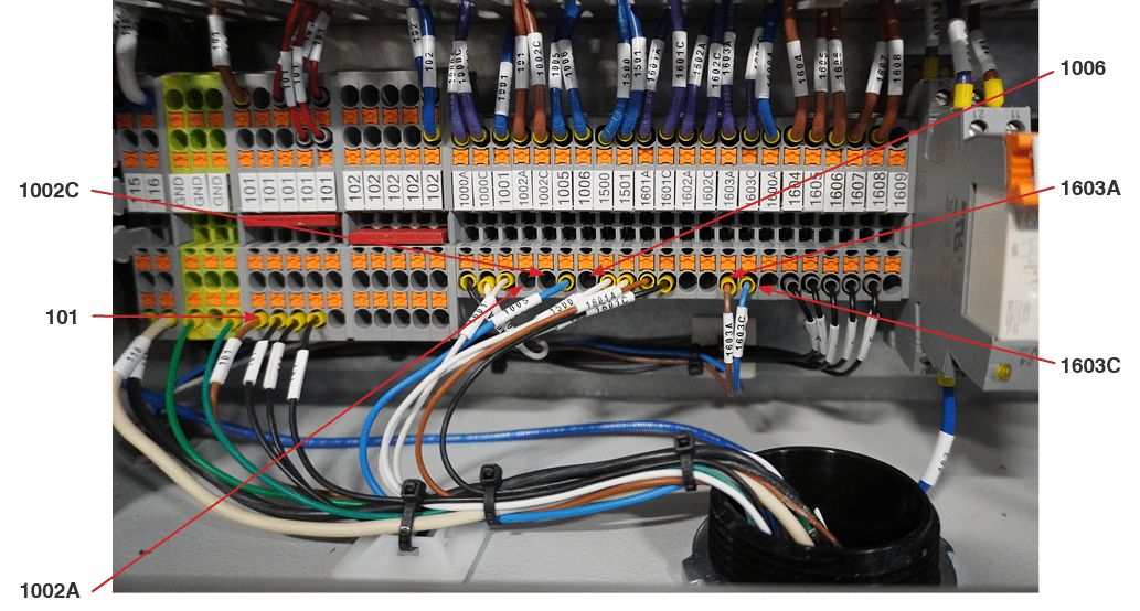
Fig. 3.3 – 2 – Electrical enclosure connections
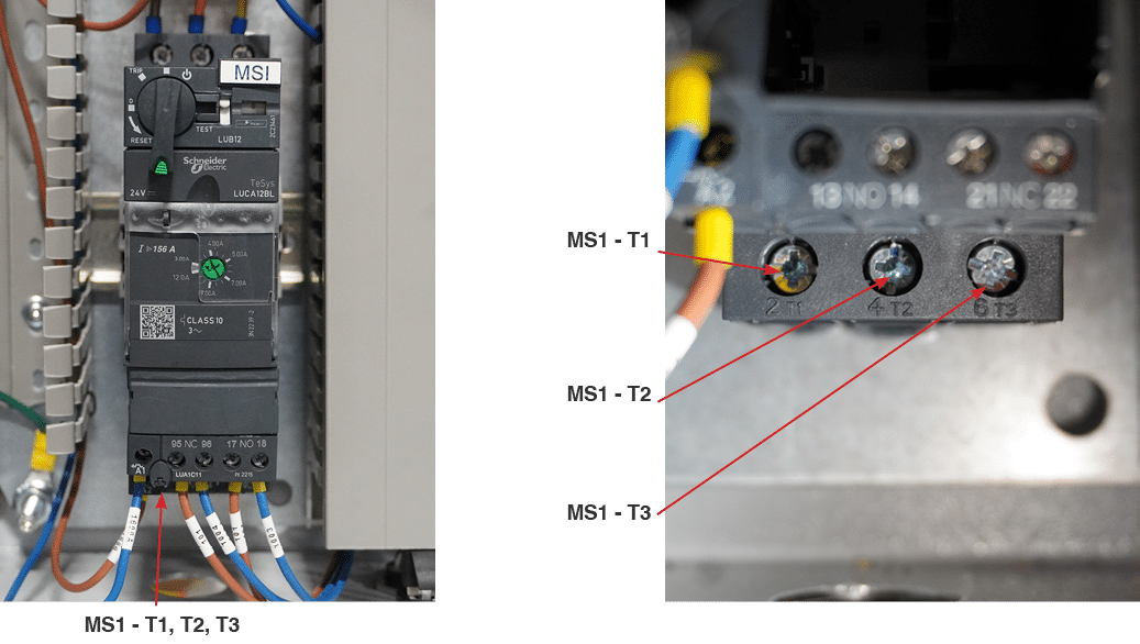
Fig. 3.3 – 3 – Additional SEG Pump connections
- Run customer supplied power (480VAC/3PH) to DS1 (Fig. 3.3 – 4) according to the system schematic in Appendix 2.
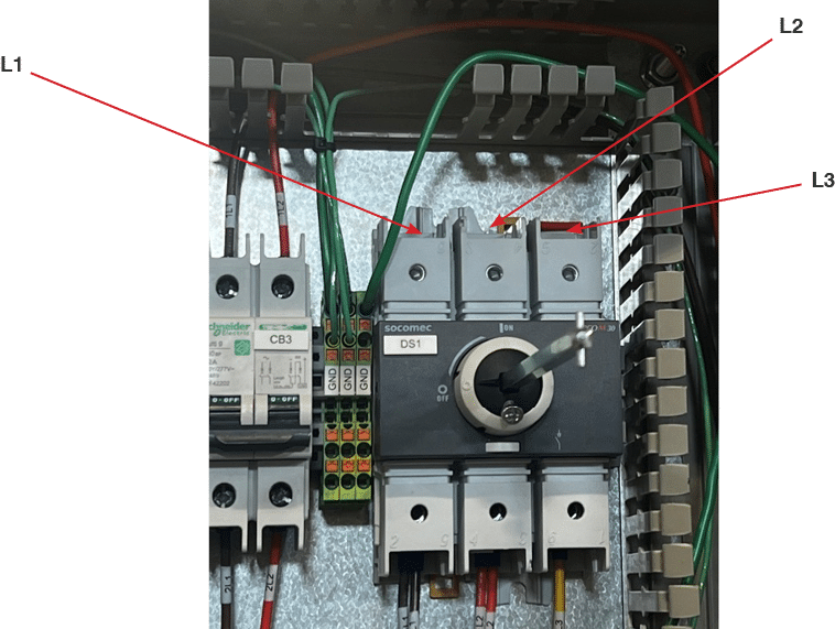
Fig. 3.3 – 4 – Customer 480VAC/3PH connection

