Assemble The Bare Arch #
- Lay the 8’ tall legs and the 12’ cross bar on the floor
- Lay one leg on the driver’s side of the conveyor and one leg on the passenger’s side of the conveyor
- Lay the cross bar perpendicular to the conveyor
- Install the hardware (fig. 1.1-1.2)
- Insert (2) ½” x 4” SS u-bolts in the holes on top of the legs
- Install ½” flat washers on bolts
- Install ½” split lock washers on bolts
- Install ½” nuts on bolts
- Apply antiseize lubricant on all threads
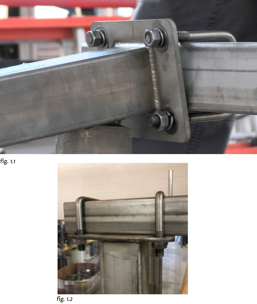
- Slide the cross bar under the u-bolts on both legs
- Tighten the u-bolts to snug
- Stand the arch up with the help from of an equipment lift
- Once your are satisfied with the placement of the arch, anchor the arch to the concrete floor
- Anchors should be a minimum of ½”-4.50”. Stainless steel is recommended
- Verify that the legs are square and plumb using a 4’ level
- Tighten all remaining hardware
Install/Connect Provided Drive Linkages #
- Apply antiseize lubricant to all threads
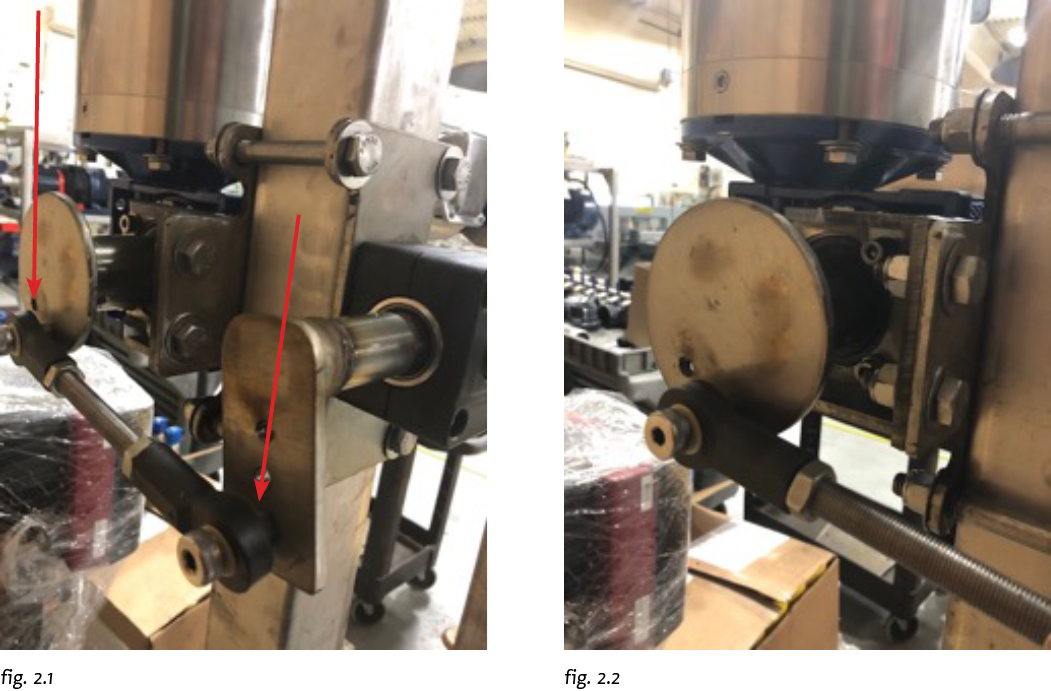
- Place the drive linkage between the oscillate flywheel that is mounted to the gearbox and the oscillate pitman arm that is mounted to the manifold assembly (fig. 2.1)
- Install the 3/8” shoulder bolt through the spherical rod end
- Install a 3/8” flat washer
- Install a 3/8” nut as a jam nut
- Thread the shoulder bolt into flywheel/pitman arm the whole way (fig. 2.2)
- While holding the shoulder bolt with allen wrench, use a 9/16” wrench and tighten the 3/8” nut
- Apply antiseize lubricant on all threads
- Repeat for the other side of the arch
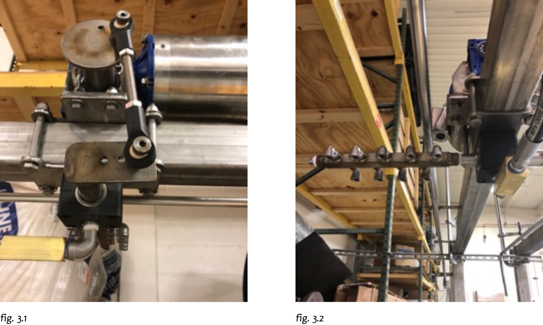
- Repeat for the top oscillator (fig. 3.1-3.2)
- Generally the top oscillating manifold is on the entrance side of the arch
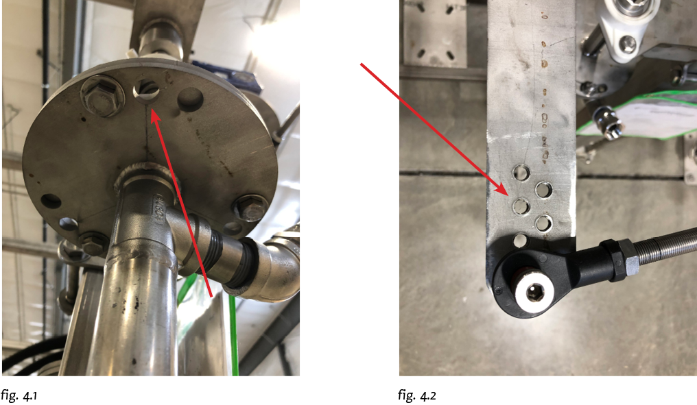
- The amount of oscillation (throw) of each manifold can be adjusted in two ways:
- Adjusting the shoulder bolt location in the driveshaft plate (fig 4.1)
- Adjusting the shoulder bolt locations on the manifold’s pitman arm (fig. 4.2)
#
Install Hoses #
- Install the stainless steel mounts for the high pressure stainless steel tubing
- When making hose connections it is best to keep the mounts on the vertical legs as close as possible to the connection points of the tubing for stability
- Evenly space the mounts across the top evenly
- Apply antiseize lubricant to all threads
- Connect the high-pressure hose from the backroom pump to the stainless steel tubing
- Connect the provided high-pressure hose from the stainless steel tubing to the manifold on both the driver and passenger sides
Wire The Electric Motor #
WARNING! To be performed by qualified electrician
- Have a qualified electrician install conduit/wire to the manifold motor
- Ensure that the junction box cover and gasket are in place and tightened evenly
- Ensure that the incoming conduit is entering the bottom of the junction box
- Follow the local/ state/ national electrical codes
Flush The Lines & Check Leaks #
- Turn on the oscillators and check for any binding in the linkage
- Adjust the oscillation speed according to your specific needs
- Turn on the pump and flush out the lines for a minimum of 10 minutes
- Install the desired nozzles onto the manifold
- Ensure that there are no leaks
- Ensure that all remaining hardware is tightened