Installation Requirements #
- The wheelblastIT requires the following components to operate
- wheelblastIT assembly
- Control system
- Water pump (owner supplied)
Space Requirements #
- Dimensions: 96”Wx 24”H x 24” D
Operating Pressures #
- Water: 12 GPM at 600-1000 PSI
Electrical Supply #
- 20 AMP 3 phase (208, 230, 240, 380 or 480vac)
- 15 AMP 120vac
What’s Included #
- (2) wheelblastIT frame assembly
- Each wheelblastIT frame assembly includes:
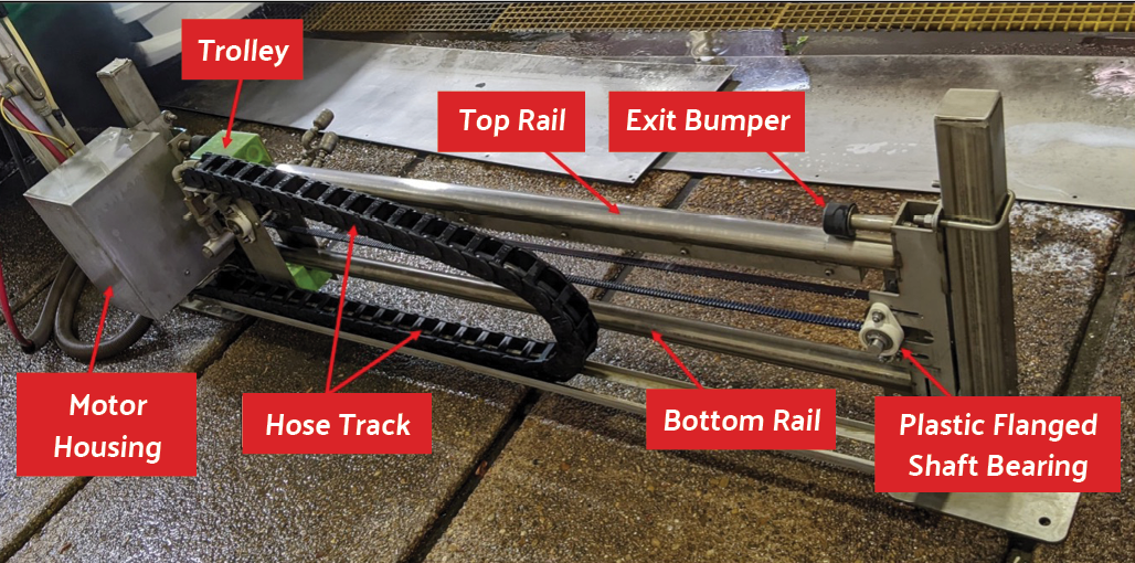
- (1) Traveling carriage (fig. 1.1)
- (1) ¾ hp Electric Motor (fig 1.2)
- (1) Gearbox
- (1) Energy chain with high-pressure hose ½’’mnpt fitting (fig 1.3)
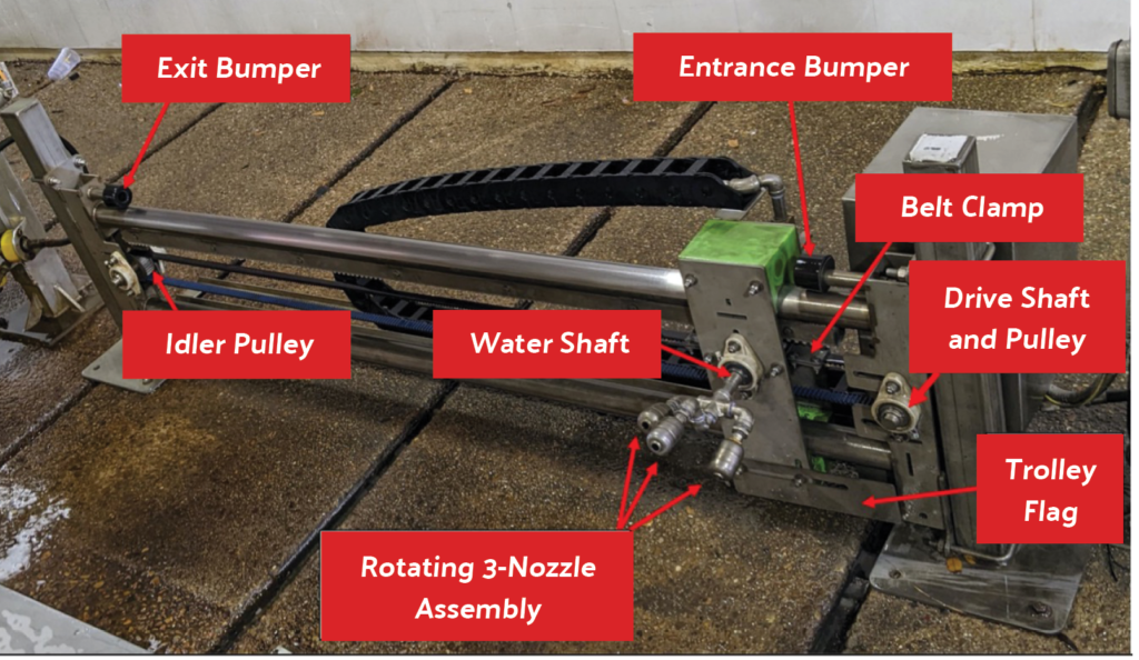
- (1) Nozzle assembly (fig 1.4)
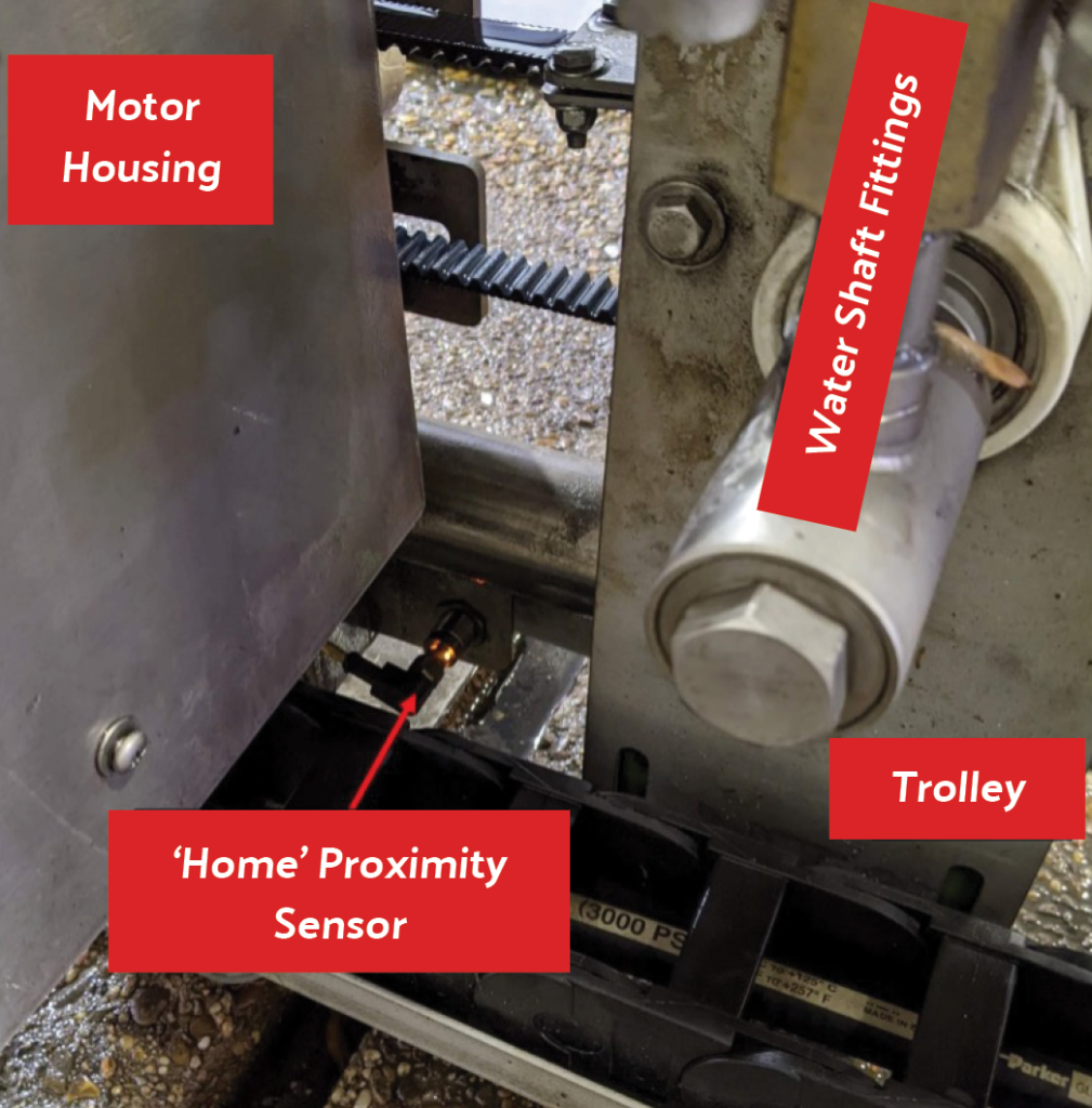
- (1) home proximity sensor
- (1) 25-meter emitter cable
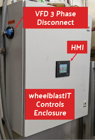
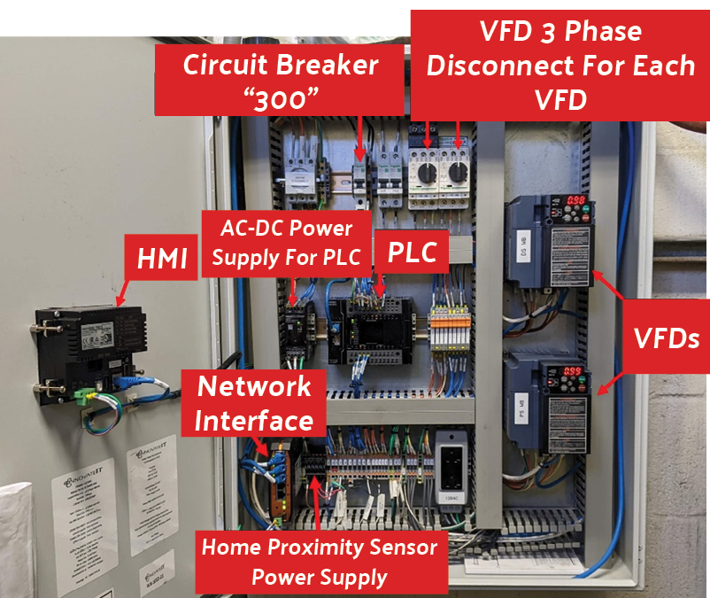
- (1) innovateIT wheelblastIT Control Box (fig. 2)
- a. 208, 230, 240, 380 or 480vac 3 phase (chosen by the customer at the time of order)
- b. 120vac or 24vac (chosen by the customer at the time of order)
- (1) Tire eye sensor or Tire pad sensor (chosen by the customer at the time of order)
- (1) 25-meter emitter cable
- (2) sensor brackets (only applicable for belt conveyors)
Tools & Materials #
- A few standard mechanic tools and a couple specific tools are needed to service and repair wheel blasters. Tools specific to wheel blasters can be created from materials found in most workshops.
- Standard Tools
- Most nuts and bolt heads are 9/16” (15 mm) in size.
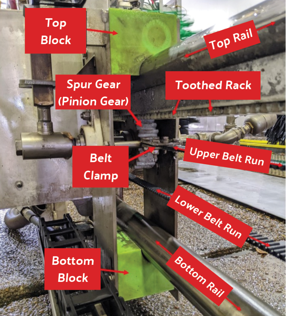
- Mount belt clamp assemblies to the trolley with 9/16” wrenches. Loosening and tightening the clamp sections securing the belt requires 7/16” wrenches.
- The “Home” proximity sensor has two low-profile 15/16” jam nuts. A 15/16” deep socket wrench is highly recommended to loosen jam nuts that were mistakenly installed with permanent red Loctite.
- Motor housing cover U-bolt nuts require a 3/4” wrench.
- All shafts take 1” shaft collars.
- Shaft collar screws take a 3/16” hex driver. A long shafted hex driver is recommended.
- Set screws for the plastic-flanged shaft bearing assemblies take a 1/8” hex driver.
- The hex head fitting at the wall side of the water shaft takes a 1-1/16” wrench. A large adjustable wrench or pipe wrench can be used.
- A small to medium sized pipe wrench is recommended when removing the 3-nozzle assembly.
- DO NOT grip the water shaft itself because it must be pulled through the 1” shaft bearings. Wrenches should instead grip the short double-male couplers at either end of the water shaft or the nozzle assembly.
- A ruler or tape measure is required to measure belt deflection.
- A hammer may be used to LIGHTLY tap and align idler pulley shaft plastic-flanged bearings.
- Specific Tools
- 1/8” probe is needed to test or set the gap between the “Home” proximity sensor and trolley flag.
- A 1/8” hex driver can be used provided it has a long enough shaft to reach between the sensor and flag
- Alternatively, a 1/8” welding rod can be used as a probe after removal of the flux material.
- 3/32” diameter 12” long probe is needed to test or set the gap between the bottom block and bottom rail and to test or set the gap between the spur gear (pinion gear) and toothed rack.
- Bend about 1.5” of one end of the probe at a right angle to reach between spur gear and rack teeth.
- A 3/32” welding rod can be adapted for use as a probe after removal of the flux material.
- 1/8” probe is needed to test or set the gap between the “Home” proximity sensor and trolley flag.
Installation Preparation #
- The unloading and movement of the wheelblastIT should be done with the use of a forklift.
- Uncrate the equipment and ensure nothing has been not damaged during transportation prior to beginning installation.
Placement – Frame Assembly #
- Locate where the equipment will be installed with your installer
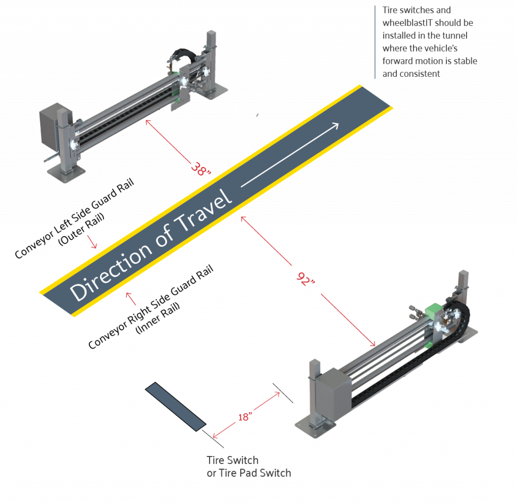
- Standard Conveyor – Driver Side
- The wheelblastIT’s frame should be 38” off the conveyor’s “left” side guide rail (outer rail)
- If attached to a rinseIT arch, the frame should be 40.5” off the conveyor’s “left” side guard rail (outer rail)
- Standard Conveyor – Passenger Side
- The wheelblastIT’s frame should be 92” off the conveyor’s “right” side guide rail (inner rail)
- If attached to a rinseIT arch, the frame should be 96.5” of the conveyor’s “right” side guard rail (inner rail)
- Standard Conveyor – Tire Eye Sensor / Tire Pad Switch
- Install the included tire sensor (chosen by the customer at the time of order). If needed, contact your service installer for assistance with installing the sensor
- Mount 18-24 inches before the traveling carriages home position
- Belt Conveyor – Driver Side
- The wheelblastIT’s frame should be 18” off the “left” side of the conveyor belt
- Belt Conveyor – Passenger Side
- The wheelblastIT’s frame should be 18” off the conveyor’s “right” side of the conveyor belt
- Belt Conveyor – Tire Eye Sensor
- Use the provided sensor brackets to mount the sensors on either side of the belt. If needed, contact your service installer for assistance with installing sensor bracket
- Mount 18-24 inches before the traveling carriages home position
- Place the protective cover over the top of the sensors
- Standard Conveyor – Driver Side
Placement – Control Cabinet #
- The innovateIT control cabinet should be mounted in the equipment room
- Take into consideration the following points
- Access to HMI screen
- Location of 3ph electric supply for the system
- Location of control wiring from tunnel controller for the system
- Location of any equipment that may be spraying water
- Take into consideration the following points
- Consider the following for the conduit connections to the control cabinet
- Do not have penetrations on the top of the cabinet
- Bottom and side penetrations are acceptable
Electrical Connection – Control Cabinet #
- Have a qualified electrician install conduit/wire from the tunnel controller to the wheelblastIT’s control box location
- Follow all local/ state/national electrical codes
wheelblastIT Indentification #